Kyocera FS-9120DN FS-9120DN/9520DN Operation Guide Rev-2 - Page 106
PRESCRIBE FRPO D0 command, 5. RS-232C Cable Connection, 5.1 Obtain a Suitable RS-232C Cable
 |
View all Kyocera FS-9120DN manuals
Add to My Manuals
Save this manual to your list of manuals |
Page 106 highlights
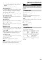
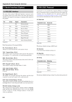
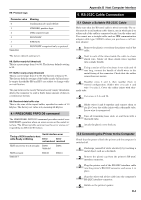
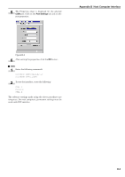
H5: Protocol logic Parameter value Meaning 0 Combination of 1 and 3 below 1 DTR/DSR, positive logic 2 DTR, negative logic 3 XON/XOFF 4 ETX/ACK 5 Table B-6 XON/XOFF recognized only as protocol The factory default setting is 0. H6: Buffer nearly-full threshold This is a percentage from 0 to 99. The factory default setting is 90. H7: Buffer nearly-empty threshold This is a percentage from 0 to 99. The factory setting is 70. The factory default settings of the buffer nearly-full and nearly-empty thresholds (H6 and H7) are subject to change without notification. The gap between the nearly-full and nearly-empty thresholds allows the computer to send a fairly large amount of data in a continuous stream. H8: Received-data buffer size This is the size of the input buffer, specified in units of 10 Kbytes. The factory-set value is 6, meaning 60 Kbytes. 4.1 PRESCRIBE FRPO D0 command The PRESCRIBE FRPO D0 command provides control over XON/XOFF operation when an error occurs on the serial interface. The following table summarizes the error status corresponding to different D0 values. Timing of XON transfer to host while Ready or Waiting Serial interface error Error Error not resolved resolved XON sent every 3 to 5 seconds D0=0 (default) D0=1 XON not sent Table B-7 D0=10 D0=11 Appendix B Host Computer Interface 5. RS-232C Cable Connection 5.1 Obtain a Suitable RS-232C Cable Make sure that the RS-232C cable is wired correctly. The cable must be a null modem cable; that is, one in which pin 2 on either end of the cable is connected to pin 3 on the other end. You cannot use a straight cable such as IBM communication adapter cable type 1502067 unless you purchase a null modem adapter. 1 Remove the plastic cover from the printer end of the cable. 2 Next to each of the wires inside the cable is a bare shield wire. Solder all these shield wires together into a single bundle. 3 Using a section of flat wire about 3 mm wide and 15 mm long, connect the bundle of shield wires to the metal facing of the connector. Check that the solder connections are secure. 4 Desolder wires 2 and 3, then resolder them in crossed configuration. Solder wire 2 to pin 3 and wire 3 to pin 2. Cover the solder joints with thermofit tube. 5 Cut wires 4, 5, 6, and 20. 6 Solder wires 5 and 6 together and connect them to pin 20. Cover the solder joints with a thermofit tube. Leave wire 4 unconnected. 7 Tape all remaining loose ends, or seal them with a thermofit tube. 8 Attach the plastic cover back on. 5.2 Connecting the Printer to the Computer Check that the power of both the printer and the computer is switched off. 1 Discharge yourself of static electricity by touching a metal object such as a doorknob. 2 Remove the plastie cap from the printer's RS-232C interface connector. 3 Plug the printer end of the RS-232C interface cable into the printer's RS-232C connector and screw it in place. 4 Plug the other end of the cable into the computer's RS-232C interface connector. 5 Switch on the printer's power. B-4
-
 1
1 -
2
-
3
-
4
-
5
-
6
-
7
-
8
-
9
-
10
-
11
-
12
-
13
-
14
-
15
-
16
-
17
-
18
-
19
-
20
-
21
-
22
-
23
-
24
-
25
-
26
-
27
-
28
-
29
-
30
-
31
-
32
-
33
-
34
-
35
-
36
-
37
-
38
-
39
-
40
-
41
-
42
-
43
-
44
-
45
-
46
-
47
-
48
-
49
-
50
-
51
-
52
-
53
-
54
-
55
-
56
-
57
-
58
-
59
-
60
-
61
-
62
-
63
-
64
-
65
-
66
-
67
-
68
-
69
-
70
-
71
-
72
-
73
-
74
-
75
-
76
-
77
-
78
-
79
-
80
-
81
-
82
-
83
-
84
-
85
-
86
-
87
-
88
-
89
-
90
-
91
-
92
-
93
-
94
-
95
-
96
-
97
-
98
-
99
-
100
-
 101
101 -
 102
102 -
 103
103 -
 104
104 -
 105
105 -
 106
106 -
 107
107 -
 108
108 -
 109
109 -
 110
110 -
 111
111 -
112
-
113
-
114
-
115
 |
 |