Kyocera FS-9120DN FS-9120DN/9520DN Operation Guide Rev-2 - Page 13
MP Multi-Purpose tray, Left cover 2
 |
View all Kyocera FS-9120DN manuals
Add to My Manuals
Save this manual to your list of manuals |
Page 13 highlights
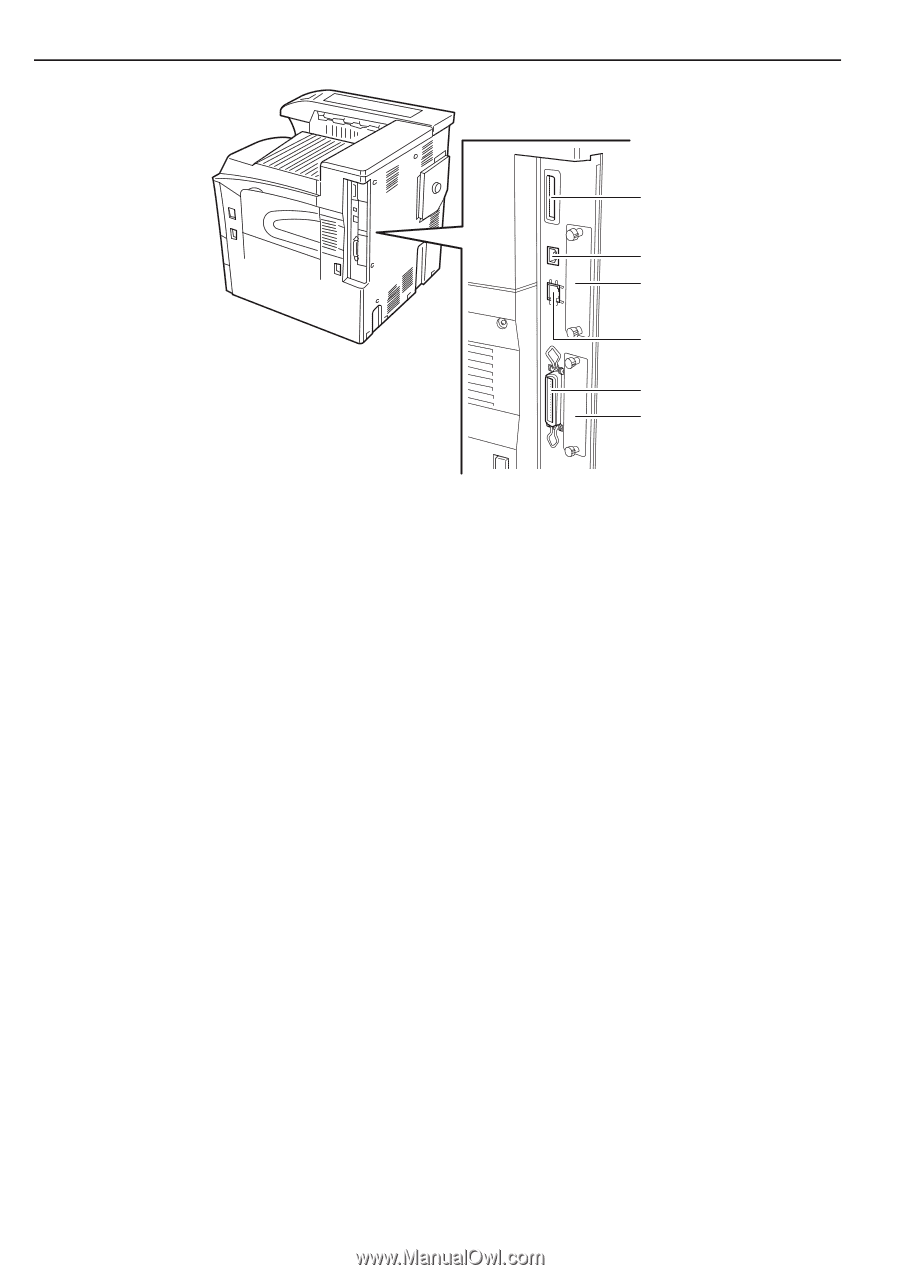
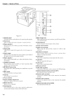
Chapter 1 Names of Parts M N O Figure 1-3 1 Operator panel Contains the keys and indicators for operating the printer. 2 Front cover Open to replace the toner container or waste toner box. 3 Paper cassette 2 Second cassette that holds up to about 500 sheets of standard paper. 4 Paper guide Adjust to the length of the paper to be set in the paper cassette. 5 Paper stopper Hold the lever and adjust the paper guide to the width of the paper to be set in the paper cassette. 6 Paper cassette 1 First cassette that holds up to about 500 sheets of standard paper. 7 Handles for transport These handles must be held by at least 4 persons when lifting or moving the printer. 8 MP (Multi-Purpose) tray Load paper here when printing onto small-size or special paper. 9 Main switch Turn ON (I) before starting to print. 0 Top tray Printed paper is stored here. A Toner container B Toner container release lever Operate to replace the toner container. C Waste toner box Waste toner is collected. D Cleaning knob Pull and push back in after toner container replacement or when print images become soiled with toner. P Q R E Main charger unit When replacing the toner container, install the grid cleaner to clean the grid. F Cleaning brush Used to clean the internal part of the printer. G Power cord connector H Option unit connector When using the option device, connect its cable to this connector. I Handles for transport These handles must be held by at least 4 persons when lifting or moving the printer. J Left cover 2 Open when a paper jam occurs inside the left cover 2. K Lock lever Pull up to open the left cover 1. L Left cover 1 Open when a paper jam occurs. M Memory card slot N USB cable connector Connect the USB cable to this connector for USB printing. O Optional network interface card slot (OPT) For optional network interface card. P Network cable connector Connect the network cable to this connector for network printing. Q Parallel cable connector Connect the parallel cable to this connector for parallel printing. R Optional hard disk unit slot (HDD) For optional hard disk unit. 1-2
-
 1
1 -
2
-
3
-
4
-
5
-
6
-
7
-
 8
8 -
 9
9 -
 10
10 -
 11
11 -
 12
12 -
 13
13 -
 14
14 -
 15
15 -
 16
16 -
 17
17 -
 18
18 -
19
-
20
-
21
-
22
-
23
-
24
-
25
-
26
-
27
-
28
-
29
-
30
-
31
-
32
-
33
-
34
-
35
-
36
-
37
-
38
-
39
-
40
-
41
-
42
-
43
-
44
-
45
-
46
-
47
-
48
-
49
-
50
-
51
-
52
-
53
-
54
-
55
-
56
-
57
-
58
-
59
-
60
-
61
-
62
-
63
-
64
-
65
-
66
-
67
-
68
-
69
-
70
-
71
-
72
-
73
-
74
-
75
-
76
-
77
-
78
-
79
-
80
-
81
-
82
-
83
-
84
-
85
-
86
-
87
-
88
-
89
-
90
-
91
-
92
-
93
-
94
-
95
-
96
-
97
-
98
-
99
-
100
-
101
-
102
-
103
-
104
-
105
-
106
-
107
-
108
-
109
-
110
-
111
-
112
-
113
-
114
-
115
 |
 |