Kyocera FS-9120DN FS-9120DN/9520DN Operation Guide Rev-2 - Page 105
Serial Interface (Option), 3.1 RS-232C Interface, RS-232C Interface Voltage Levels
 |
View all Kyocera FS-9120DN manuals
Add to My Manuals
Save this manual to your list of manuals |
Page 105 highlights
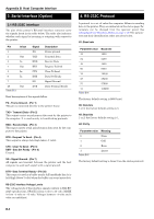
Appendix B Host Computer Interface 3. Serial Interface (Option) 3.1 RS-232C Interface The pins of the printer's RS-232C interface connector carry the signals listed in the table below. The table also indicates whether each signal is incoming or outgoing with respect to the printer. Pin 1 2 3 4 5 6 7 20 Table B-3 In/out Out In Out In In Out Signal FG TXD RXD RTS CTS DSR SG DTR Description Frame ground Transmit Data Receive Data Request To Send Clear To Send Data Set Ready Signal Ground Data Terminal Ready Brief descriptions of the signals follow. FG - Frame Ground - (Pin 1) This pin is connected directly to the printer frame. TXD - Transmit Data - (Pin 2) This output carries asynchronous data sent by the printer to the computer. It is used mainly in handshaking protocols. RXD - Receive Data - (Pin 3) This input carries serial asynchronous data sent by the computer to the printer. RTS - Request To Send - (Pin 4) This output is always held high (above 3 volts). CTS - Clear To Send - (Pin 5) DSR - Data Set Ready - (Pin 6) Unused. SG - Signal Ground - (Pin 7) All signals can transmit between the printer and the host computer to send each signal with a signal ground. DTR - Data Terminal Ready - (Pin 20) This output is used as a buffer nearly-full handshake line. It is held high (above 3 volts) when the buffer can accept more data. RS-232C Interface Voltage Levels The voltage levels of the interface signals conform to EIA RS232C specifications. SPACE is from 3 volts to 15 volts. MARK is from -3 volts to -15 volts. Voltages between -3 volts and 3 volts are undefined. 4. RS-232C Protocol A protocol is a set of rules the computer follows in sending data to the printer. They are indicated on the status page. Parameters can be changed from the operator panel. See Changing Serial Interface Modes on page 3-19. The parameters and their identification codes are given below. H1: Baud rate Parameter value Baud rate 12 1200 24 2400 48 4800 96 9600 19 19200 38 38400 57 57600 11 Table B-4 115200 The factory default setting is 9600 baud. H2: Data bits 7 or 8; the factory default setting is 8. H3: Stop bits 1 or 2; the factory default setting is 1. H4: Parity Parameter value Meaning 0 None 1 Odd 2 Even 3 Table B-5 Ignore The factory default setting is None (0 on the status printout). B-3
-
 1
1 -
2
-
3
-
4
-
5
-
6
-
7
-
8
-
9
-
10
-
11
-
12
-
13
-
14
-
15
-
16
-
17
-
18
-
19
-
20
-
21
-
22
-
23
-
24
-
25
-
26
-
27
-
28
-
29
-
30
-
31
-
32
-
33
-
34
-
35
-
36
-
37
-
38
-
39
-
40
-
41
-
42
-
43
-
44
-
45
-
46
-
47
-
48
-
49
-
50
-
51
-
52
-
53
-
54
-
55
-
56
-
57
-
58
-
59
-
60
-
61
-
62
-
63
-
64
-
65
-
66
-
67
-
68
-
69
-
70
-
71
-
72
-
73
-
74
-
75
-
76
-
77
-
78
-
79
-
80
-
81
-
82
-
83
-
84
-
85
-
86
-
87
-
88
-
89
-
90
-
91
-
92
-
93
-
94
-
95
-
96
-
97
-
98
-
99
-
 100
100 -
 101
101 -
 102
102 -
 103
103 -
 104
104 -
 105
105 -
 106
106 -
 107
107 -
 108
108 -
 109
109 -
 110
110 -
111
-
112
-
113
-
114
-
115
 |
 |