Netgear GS110TP GS108T/ GS110TP Smart Switch Software Administration Manual - Page 129
Interface Queue Configuration, Interface Shaping Rate, Cancel, Apply, CoS tab, and then click
 |
UPC - 606449069129
View all Netgear GS110TP manuals
Add to My Manuals
Save this manual to your list of manuals |
Page 129 highlights
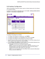
GS108T and GS110TP Smart Switch Software Administration Manual 6. From the Interface Shaping Rate field, specify the maximum bandwidth allowed on the selected interface(s). This setting is typically used to shape the outbound transmission rate in increments of 64 kbps. This value is controlled independently of any per-queue maximum bandwidth configuration. It is effectively a second-level shaping mechanism. The default value is 0, in increments of 16. A value of 0 means the maximum is unlimited. 7. Click Cancel to cancel the configuration on the screen and reset the data on the screen to the latest value of the switch. 8. If you make changes to the page, click Apply to apply the changes to the system. Interface Queue Configuration Use the Interface Queue Configuration page to define what a particular queue does by configuring switch egress queues. User-configurable parameters control the amount of bandwidth used by the queue, the queue depth during times of congestion, and the scheduling of packet transmission from the set of all queues on a port. Each port has its own CoS queue-related configuration. The configuration process is simplified by allowing each CoS queue parameter to be configured globally or per-port. A global configuration change is automatically applied to all ports in the system. To display the Interface Queue Configuration page, click the QoS CoS tab, and then click the Advanced Interface Queue Configuration link. To configure CoS queue settings for an interface: 1. To configure CoS queue settings for a physical port, click PORTS. 2. To configure CoS queue settings for a Link Aggregation Group (LAG), click LAGS. Chapter 4: Configuring Quality of Service | 129
-
 1
1 -
2
-
3
-
4
-
5
-
6
-
7
-
8
-
9
-
10
-
11
-
12
-
13
-
14
-
15
-
16
-
17
-
18
-
19
-
20
-
21
-
22
-
23
-
24
-
25
-
26
-
27
-
28
-
29
-
30
-
31
-
32
-
33
-
34
-
35
-
36
-
37
-
38
-
39
-
40
-
41
-
42
-
43
-
44
-
45
-
46
-
47
-
48
-
49
-
50
-
51
-
52
-
53
-
54
-
55
-
56
-
57
-
58
-
59
-
60
-
61
-
62
-
63
-
64
-
65
-
66
-
67
-
68
-
69
-
70
-
71
-
72
-
73
-
74
-
75
-
76
-
77
-
78
-
79
-
80
-
81
-
82
-
83
-
84
-
85
-
86
-
87
-
88
-
89
-
90
-
91
-
92
-
93
-
94
-
95
-
96
-
97
-
98
-
99
-
100
-
101
-
102
-
103
-
104
-
105
-
106
-
107
-
108
-
109
-
110
-
111
-
112
-
113
-
114
-
115
-
116
-
117
-
118
-
119
-
120
-
121
-
122
-
123
-
 124
124 -
 125
125 -
 126
126 -
 127
127 -
 128
128 -
 129
129 -
 130
130 -
 131
131 -
 132
132 -
 133
133 -
 134
134 -
135
-
136
-
137
-
138
-
139
-
140
-
141
-
142
-
143
-
144
-
145
-
146
-
147
-
148
-
149
-
150
-
151
-
152
-
153
-
154
-
155
-
156
-
157
-
158
-
159
-
160
-
161
-
162
-
163
-
164
-
165
-
166
-
167
-
168
-
169
-
170
-
171
-
172
-
173
-
174
-
175
-
176
-
177
-
178
-
179
-
180
-
181
-
182
-
183
-
184
-
185
-
186
-
187
-
188
-
189
-
190
-
191
-
192
-
193
-
194
-
195
-
196
-
197
-
198
-
199
-
200
-
201
-
202
-
203
-
204
-
205
-
206
-
207
-
208
-
209
-
210
-
211
-
212
-
213
-
214
-
215
-
216
-
217
-
218
-
219
-
220
-
221
-
222
-
223
-
224
-
225
-
226
-
227
-
228
-
229
-
230
-
231
-
232
-
233
-
234
-
235
-
236
-
237
-
238
-
239
-
240
-
241
-
242
-
243
-
244
-
245
-
246
-
247
-
248
-
249
-
250
-
251
-
252
-
253
-
254
-
255
-
256
-
257
-
258
-
259
-
260
-
261
-
262
-
263
-
264
-
265
-
266
-
267
-
268
-
269
 |
 |
