Netgear GS110TP GS108T/ GS110TP Smart Switch Software Administration Manual - Page 96
Cancel, Apply, Refresh
 |
UPC - 606449069129
View all Netgear GS110TP manuals
Add to My Manuals
Save this manual to your list of manuals |
Page 96 highlights
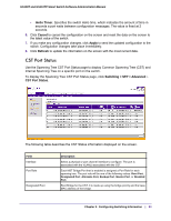
GS108T and GS110TP Smart Switch Software Administration Manual 5. Click Cancel to cancel the configuration on the screen and reset the data on the screen to the latest value of the switch 6. If you make any configuration changes, click Apply to send the updated configuration to the switch. Configuration changes occur immediately. The following table describes the STP Status information displayed on the screen. Field Description Bridge Identifier The bridge identifier for the CST. It is made up using the bridge priority and the base MAC address of the bridge. Time Since Topology Change The time in seconds since the topology of the CST last changed. Topology Change Count The number of times the topology has changed for the CST. Topology Change Designated Root The value of the topology change parameter for the switch indicating if a topology change is in progress on any port assigned to the CST. The value is either True or False. The bridge identifier of the root bridge. It is made up from the bridge priority and the base MAC address of the bridge. Root Path Cost Root Port Path cost to the Designated Root for the CST. Port to access the Designated Root for the CST. Max Age (secs) Forward Delay (secs) Hold TIme (secs) CST Regional Root CST Path Cost Specifies the bridge maximum age for CST. The value must be less than or equal to (2 X Bridge Forward Delay) - 1 and greater than or equal to 2 X (Bridge Hello Time +1). Derived value of the Root Port Bridge Forward Delay parameter. Minimum time between transmission of Configuration BPDUs. Priority and base MAC address of the CST Regional Root. Path Cost to the CST tree Regional Root. Click Refresh to update the information on the screen with the most current data. Chapter 3: Configuring Switching Information | 29
-
 1
1 -
2
-
3
-
4
-
5
-
6
-
7
-
8
-
9
-
10
-
11
-
12
-
13
-
14
-
15
-
16
-
17
-
18
-
19
-
20
-
21
-
22
-
23
-
24
-
25
-
26
-
27
-
28
-
29
-
30
-
31
-
32
-
33
-
34
-
35
-
36
-
37
-
38
-
39
-
40
-
41
-
42
-
43
-
44
-
45
-
46
-
47
-
48
-
49
-
50
-
51
-
52
-
53
-
54
-
55
-
56
-
57
-
58
-
59
-
60
-
61
-
62
-
63
-
64
-
65
-
66
-
67
-
68
-
69
-
70
-
71
-
72
-
73
-
74
-
75
-
76
-
77
-
78
-
79
-
80
-
81
-
82
-
83
-
84
-
85
-
86
-
87
-
88
-
89
-
90
-
 91
91 -
 92
92 -
 93
93 -
 94
94 -
 95
95 -
 96
96 -
 97
97 -
 98
98 -
 99
99 -
 100
100 -
 101
101 -
102
-
103
-
104
-
105
-
106
-
107
-
108
-
109
-
110
-
111
-
112
-
113
-
114
-
115
-
116
-
117
-
118
-
119
-
120
-
121
-
122
-
123
-
124
-
125
-
126
-
127
-
128
-
129
-
130
-
131
-
132
-
133
-
134
-
135
-
136
-
137
-
138
-
139
-
140
-
141
-
142
-
143
-
144
-
145
-
146
-
147
-
148
-
149
-
150
-
151
-
152
-
153
-
154
-
155
-
156
-
157
-
158
-
159
-
160
-
161
-
162
-
163
-
164
-
165
-
166
-
167
-
168
-
169
-
170
-
171
-
172
-
173
-
174
-
175
-
176
-
177
-
178
-
179
-
180
-
181
-
182
-
183
-
184
-
185
-
186
-
187
-
188
-
189
-
190
-
191
-
192
-
193
-
194
-
195
-
196
-
197
-
198
-
199
-
200
-
201
-
202
-
203
-
204
-
205
-
206
-
207
-
208
-
209
-
210
-
211
-
212
-
213
-
214
-
215
-
216
-
217
-
218
-
219
-
220
-
221
-
222
-
223
-
224
-
225
-
226
-
227
-
228
-
229
-
230
-
231
-
232
-
233
-
234
-
235
-
236
-
237
-
238
-
239
-
240
-
241
-
242
-
243
-
244
-
245
-
246
-
247
-
248
-
249
-
250
-
251
-
252
-
253
-
254
-
255
-
256
-
257
-
258
-
259
-
260
-
261
-
262
-
263
-
264
-
265
-
266
-
267
-
268
-
269
 |
 |
