Toshiba Qosmio G30 PQG31C-HD202EF Users Manual Canada; English - Page 202
Seat the memory module cover and secure it with one screw., Install the battery pack. Refer
 |
View all Toshiba Qosmio G30 PQG31C-HD202EF manuals
Add to My Manuals
Save this manual to your list of manuals |
Page 202 highlights
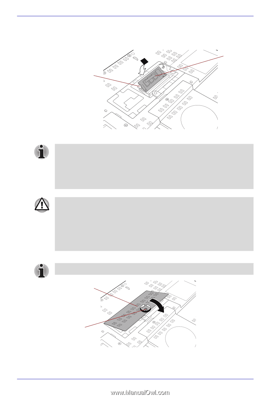
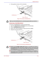
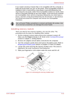
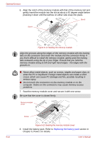
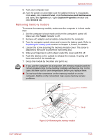
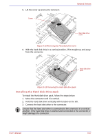
Optional Devices 6. Align the notch of the memory module with that of the memory slot and gently insert the module into the slot at about a 45 degree angle before pressing it down until the latches on either side snap into place. Slot B Slot A Figure 9-12 Seating the memory module Align the grooves along the edges of the memory module with the locking tabs on the connector and insert the module into the connector firmly. If you find it difficult to install the memory module, gently prize the locking tabs outwards using the tip of your finger. Ensure that you hold the memory module along its left and right hand edges - the edges with the grooves in. ■ Never allow metal objects, such as screws, staples and paper clips, to enter the PC or keyboard. Foreign metal objects can create a short circuit, which can cause PC damage and fire, possibly resulting in serious injury. ■ Do not touch the connectors on the memory module or on the computer. Debris on the connectors may cause memory access problems. 7. Seat the memory module cover and secure it with one screw. Be sure that the cover is closed firmly. Memory module cover Screw Figure 9-13 Seating the memory module cover 8. Install the battery pack. Refer to Replacing the battery pack section in Chapter 6, Power, for details. 9-14 User's Manual
-
 1
1 -
2
-
3
-
4
-
5
-
6
-
7
-
8
-
9
-
10
-
11
-
12
-
13
-
14
-
15
-
16
-
17
-
18
-
19
-
20
-
21
-
22
-
23
-
24
-
25
-
26
-
27
-
28
-
29
-
30
-
31
-
32
-
33
-
34
-
35
-
36
-
37
-
38
-
39
-
40
-
41
-
42
-
43
-
44
-
45
-
46
-
47
-
48
-
49
-
50
-
51
-
52
-
53
-
54
-
55
-
56
-
57
-
58
-
59
-
60
-
61
-
62
-
63
-
64
-
65
-
66
-
67
-
68
-
69
-
70
-
71
-
72
-
73
-
74
-
75
-
76
-
77
-
78
-
79
-
80
-
81
-
82
-
83
-
84
-
85
-
86
-
87
-
88
-
89
-
90
-
91
-
92
-
93
-
94
-
95
-
96
-
97
-
98
-
99
-
100
-
101
-
102
-
103
-
104
-
105
-
106
-
107
-
108
-
109
-
110
-
111
-
112
-
113
-
114
-
115
-
116
-
117
-
118
-
119
-
120
-
121
-
122
-
123
-
124
-
125
-
126
-
127
-
128
-
129
-
130
-
131
-
132
-
133
-
134
-
135
-
136
-
137
-
138
-
139
-
140
-
141
-
142
-
143
-
144
-
145
-
146
-
147
-
148
-
149
-
150
-
151
-
152
-
153
-
154
-
155
-
156
-
157
-
158
-
159
-
160
-
161
-
162
-
163
-
164
-
165
-
166
-
167
-
168
-
169
-
170
-
171
-
172
-
173
-
174
-
175
-
176
-
177
-
178
-
179
-
180
-
181
-
182
-
183
-
184
-
185
-
186
-
187
-
188
-
189
-
190
-
191
-
192
-
193
-
194
-
195
-
196
-
 197
197 -
 198
198 -
 199
199 -
 200
200 -
 201
201 -
 202
202 -
 203
203 -
 204
204 -
 205
205 -
 206
206 -
 207
207 -
208
-
209
-
210
-
211
-
212
-
213
-
214
-
215
-
216
-
217
-
218
-
219
-
220
-
221
-
222
-
223
-
224
-
225
-
226
-
227
-
228
-
229
-
230
-
231
-
232
-
233
-
234
-
235
-
236
-
237
-
238
-
239
-
240
-
241
-
242
-
243
-
244
-
245
-
246
-
247
-
248
-
249
-
250
-
251
-
252
-
253
-
254
-
255
-
256
-
257
-
258
-
259
-
260
-
261
-
262
-
263
-
264
-
265
-
266
-
267
-
268
-
269
-
270
-
271
-
272
-
273
-
274
-
275
-
276
-
277
-
278
-
279
-
280
-
281
-
282
-
283
-
284
-
285
-
286
-
287
-
288
-
289
-
290
-
291
-
292
-
293
-
294
-
295
-
296
-
297
-
298
-
299
-
300
-
301
-
302
-
303
-
304
-
305
-
306
-
307
-
308
-
309
-
310
-
311
-
312
-
313
-
314
-
315
-
316
-
317
-
318
 |
 |