Yamaha AW2816 Owner's Manual - Page 19
Installing I/O card, About I/O cards, Installation procedure - adat
 |
View all Yamaha AW2816 manuals
Add to My Manuals
Save this manual to your list of manuals |
Page 19 highlights
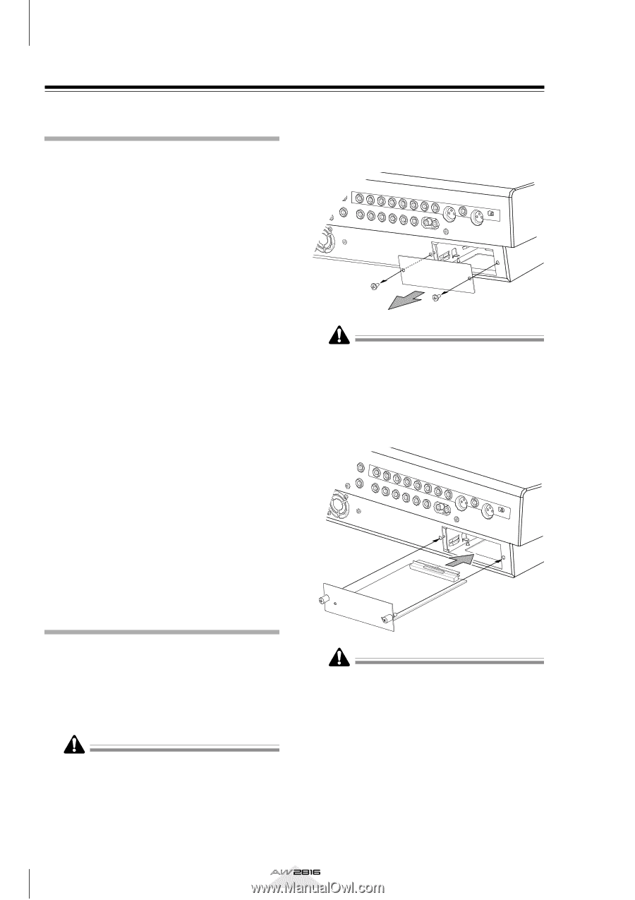
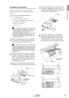
Before you begin Installing I/O card About I/O cards I/O cards compatible with the Yamaha mini-YGDAI format can be installed in the OPTION I/O slot located on the rear panel of the AW2816 in order to add input/output ports. For example by installing an ADAT format compatible I/O card into an OPTION I/ O slot, you can transmit/receive eight channels of digital audio to/from an ADAT format digital recorder. At present, the following types of I/O cards can be used. q MY8-AT This card transmits and receives eight channels of Alesis ADAT format digital signals. q MY8-TD This card transmits and receives eight channels of TASCAM format digital signals. q MY8-AE This card transmits and receives eight channels of AES/EBU format digital signals. q MY8-AD This is an A/D card with eight channels of analog input jacks (balanced TRS phone jacks). q MY4-AD This is an A/D card with four channels of analog input jacks (balanced XLR jacks). q MY4-DA This is a D/A card with four channels of analog output jacks (balanced XLR jacks). For up-to-date information on available MY cards, contact your local Yamaha distributor or check the following website. Installation procedure Please carefully read the cautions for installing optional devices, given at the beginning of this manual. 1 Make sure that the power of the AW2816 is turned off. For safety's sake, disconnect the power cable from the AC outlet. 2 From the OPTION I/O slot located on the rear panel of the AW2816, remove the two screws that hold the cover in place. Please keep the cover and screws you removed in a safe place. 3 Slide the I/O card along the rails inside the slot until it clicks into place. 4 Tighten the two screws included with the I/O card to fasten the card securely. Please note that if the screws are loose, the card may not be grounded correctly. Always switch off the power for the main unit and all peripherals, unplug the power cord for the main unit from the outlet, then disconnect the cables connecting the main unit with the peripherals before starting installation work. 10 Operation section
-
 1
1 -
2
-
3
-
4
-
5
-
6
-
7
-
8
-
9
-
10
-
11
-
12
-
13
-
 14
14 -
 15
15 -
 16
16 -
 17
17 -
 18
18 -
 19
19 -
 20
20 -
 21
21 -
 22
22 -
 23
23 -
 24
24 -
25
-
26
-
27
-
28
-
29
-
30
-
31
-
32
-
33
-
34
-
35
-
36
-
37
-
38
-
39
-
40
-
41
-
42
-
43
-
44
-
45
-
46
-
47
-
48
-
49
-
50
-
51
-
52
-
53
-
54
-
55
-
56
-
57
-
58
-
59
-
60
-
61
-
62
-
63
-
64
-
65
-
66
-
67
-
68
-
69
-
70
-
71
-
72
-
73
-
74
-
75
-
76
-
77
-
78
-
79
-
80
-
81
-
82
-
83
-
84
-
85
-
86
-
87
-
88
-
89
-
90
-
91
-
92
-
93
-
94
-
95
-
96
-
97
-
98
-
99
-
100
-
101
-
102
-
103
-
104
-
105
-
106
-
107
-
108
-
109
-
110
-
111
-
112
-
113
-
114
-
115
-
116
-
117
-
118
-
119
-
120
-
121
-
122
-
123
-
124
-
125
-
126
-
127
-
128
-
129
-
130
-
131
-
132
-
133
-
134
-
135
-
136
-
137
-
138
-
139
-
140
-
141
-
142
-
143
-
144
-
145
-
146
-
147
-
148
-
149
-
150
-
151
-
152
-
153
-
154
-
155
-
156
-
157
-
158
-
159
-
160
-
161
-
162
-
163
-
164
-
165
-
166
-
167
-
168
-
169
-
170
-
171
-
172
-
173
-
174
-
175
-
176
-
177
-
178
-
179
-
180
-
181
-
182
-
183
-
184
-
185
-
186
-
187
-
188
-
189
-
190
-
191
-
192
-
193
-
194
-
195
-
196
-
197
-
198
-
199
-
200
-
201
-
202
-
203
-
204
-
205
-
206
-
207
-
208
-
209
-
210
-
211
-
212
-
213
-
214
-
215
-
216
-
217
-
218
-
219
-
220
-
221
-
222
-
223
-
224
-
225
-
226
-
227
-
228
-
229
-
230
-
231
-
232
-
233
-
234
-
235
-
236
-
237
-
238
-
239
-
240
-
241
-
242
-
243
-
244
-
245
-
246
-
247
-
248
-
249
-
250
-
251
-
252
-
253
-
254
-
255
-
256
-
257
-
258
-
259
-
260
-
261
-
262
-
263
-
264
-
265
-
266
-
267
-
268
-
269
-
270
-
271
-
272
-
273
-
274
-
275
-
276
-
277
-
278
-
279
-
280
-
281
-
282
-
283
-
284
-
285
-
286
-
287
-
288
-
289
-
290
-
291
-
292
-
293
-
294
-
295
-
296
-
297
-
298
-
299
-
300
-
301
-
302
-
303
-
304
-
305
-
306
-
307
-
308
-
309
-
310
-
311
-
312
-
313
-
314
-
315
-
316
-
317
-
318
-
319
-
320
-
321
-
322
-
323
-
324
-
325
-
326
-
327
-
328
-
329
-
330
-
331
-
332
-
333
-
334
-
335
-
336
-
337
-
338
-
339
-
340
-
341
-
342
-
343
-
344
-
345
-
346
-
347
-
348
-
349
-
350
-
351
-
352
-
353
-
354
-
355
-
356
-
357
-
358
-
359
-
360
-
361
-
362
-
363
-
364
-
365
-
366
-
367
-
368
-
369
-
370
-
371
-
372
-
373
-
374
-
375
-
376
-
377
-
378
-
379
-
380
-
381
-
382
-
383
-
384
-
385
-
386
-
387
-
388
-
389
-
390
-
391
-
392
-
393
-
394
-
395
-
396
-
397
-
398
-
399
-
400
-
401
-
402
-
403
-
404
-
405
-
406
-
407
-
408
-
409
-
410
-
411
-
412
-
413
-
414
-
415
-
416
-
417
-
418
-
419
-
420
 |
 |