Yamaha AW2816 Owner's Manual - Page 53
Using the digital MTR as the word clock master, Using a DAT recorder or MD recorder as
 |
View all Yamaha AW2816 manuals
Add to My Manuals
Save this manual to your list of manuals |
Page 53 highlights
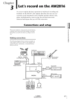
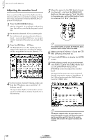
• Using the digital MTR as the word clock master In this case, the digital MTR will be the word clock master, and the AW2816 will follow the word clock included in the input signal from the digital I/O card. Turn on one of the SLOT 1/2-7/8 buttons. OPTION I/O SLOT Word clock AW2816 (word clock slave) WORD CLOCK SOURCE = SLOT 1/2-7/8 Digital I/O card Digital MTR (word clock master) Set the digital MTR so that it will operate using its own internal clock. • Using a DAT recorder or MD recorder as the word clock master If you want to record the signal from a DAT recorder or MD recorder into the AW2816 via the DIGITAL STEREO IN jack, turn on the D.ST IN button. DIGITAL STEREO IN jack Word clock 00.00.00.00 DAT AW2816 DIGITAL (word clock slave) STEREO OUT jack WORD CLOCK SOURCE = D.ST IN DAT recorder (word clock master) Most consumer DAT recorders and MD recorders are designed to forcibly lock to the word clock of the input signal during recording. Such DAT recorders can be used as a word clock master only during playback. 3 After selecting the appropriate button, press the [ENTER] key. The AW2816 will switch to the specified clock source. The sampling frequency of the signal currently selected as the clock source will be indicated by the Fs (sampling frequency) field in the upper left of the display. 3 • If you are using the internal clock of the AW2816 as the clock source, the sampling frequency selected when you created the current song will be the sampling frequency of the entire system. • If you want the AW2816 to follow an external clock source, you must make sure that the sampling frequency of the song matches the value displayed in the Fs field. If these values are different, the pitch may change when you set the clock source back to "INT" (internal clock). • A certain amount of time may be required for the AW2816 to switch clock sources, and there may be silence during this time. • After switching the clock source, verify that an X or/ symbol is not superimposed on the button you selected in step 3. If an X or/symbol is displayed, or if an error message is displayed, check whether the clock setting and connections of the external device is appropriate. Let's record on the AW2816 Operation section 45
-
 1
1 -
2
-
3
-
4
-
5
-
6
-
7
-
8
-
9
-
10
-
11
-
12
-
13
-
14
-
15
-
16
-
17
-
18
-
19
-
20
-
21
-
22
-
23
-
24
-
25
-
26
-
27
-
28
-
29
-
30
-
31
-
32
-
33
-
34
-
35
-
36
-
37
-
38
-
39
-
40
-
41
-
42
-
43
-
44
-
45
-
46
-
47
-
 48
48 -
 49
49 -
 50
50 -
 51
51 -
 52
52 -
 53
53 -
 54
54 -
 55
55 -
 56
56 -
 57
57 -
 58
58 -
59
-
60
-
61
-
62
-
63
-
64
-
65
-
66
-
67
-
68
-
69
-
70
-
71
-
72
-
73
-
74
-
75
-
76
-
77
-
78
-
79
-
80
-
81
-
82
-
83
-
84
-
85
-
86
-
87
-
88
-
89
-
90
-
91
-
92
-
93
-
94
-
95
-
96
-
97
-
98
-
99
-
100
-
101
-
102
-
103
-
104
-
105
-
106
-
107
-
108
-
109
-
110
-
111
-
112
-
113
-
114
-
115
-
116
-
117
-
118
-
119
-
120
-
121
-
122
-
123
-
124
-
125
-
126
-
127
-
128
-
129
-
130
-
131
-
132
-
133
-
134
-
135
-
136
-
137
-
138
-
139
-
140
-
141
-
142
-
143
-
144
-
145
-
146
-
147
-
148
-
149
-
150
-
151
-
152
-
153
-
154
-
155
-
156
-
157
-
158
-
159
-
160
-
161
-
162
-
163
-
164
-
165
-
166
-
167
-
168
-
169
-
170
-
171
-
172
-
173
-
174
-
175
-
176
-
177
-
178
-
179
-
180
-
181
-
182
-
183
-
184
-
185
-
186
-
187
-
188
-
189
-
190
-
191
-
192
-
193
-
194
-
195
-
196
-
197
-
198
-
199
-
200
-
201
-
202
-
203
-
204
-
205
-
206
-
207
-
208
-
209
-
210
-
211
-
212
-
213
-
214
-
215
-
216
-
217
-
218
-
219
-
220
-
221
-
222
-
223
-
224
-
225
-
226
-
227
-
228
-
229
-
230
-
231
-
232
-
233
-
234
-
235
-
236
-
237
-
238
-
239
-
240
-
241
-
242
-
243
-
244
-
245
-
246
-
247
-
248
-
249
-
250
-
251
-
252
-
253
-
254
-
255
-
256
-
257
-
258
-
259
-
260
-
261
-
262
-
263
-
264
-
265
-
266
-
267
-
268
-
269
-
270
-
271
-
272
-
273
-
274
-
275
-
276
-
277
-
278
-
279
-
280
-
281
-
282
-
283
-
284
-
285
-
286
-
287
-
288
-
289
-
290
-
291
-
292
-
293
-
294
-
295
-
296
-
297
-
298
-
299
-
300
-
301
-
302
-
303
-
304
-
305
-
306
-
307
-
308
-
309
-
310
-
311
-
312
-
313
-
314
-
315
-
316
-
317
-
318
-
319
-
320
-
321
-
322
-
323
-
324
-
325
-
326
-
327
-
328
-
329
-
330
-
331
-
332
-
333
-
334
-
335
-
336
-
337
-
338
-
339
-
340
-
341
-
342
-
343
-
344
-
345
-
346
-
347
-
348
-
349
-
350
-
351
-
352
-
353
-
354
-
355
-
356
-
357
-
358
-
359
-
360
-
361
-
362
-
363
-
364
-
365
-
366
-
367
-
368
-
369
-
370
-
371
-
372
-
373
-
374
-
375
-
376
-
377
-
378
-
379
-
380
-
381
-
382
-
383
-
384
-
385
-
386
-
387
-
388
-
389
-
390
-
391
-
392
-
393
-
394
-
395
-
396
-
397
-
398
-
399
-
400
-
401
-
402
-
403
-
404
-
405
-
406
-
407
-
408
-
409
-
410
-
411
-
412
-
413
-
414
-
415
-
416
-
417
-
418
-
419
-
420
 |
 |
