Yamaha AW2816 Owner's Manual - Page 57
In the INPUT MONITOR area, make sure, While playing sounds on the instrument
 |
View all Yamaha AW2816 manuals
Add to My Manuals
Save this manual to your list of manuals |
Page 57 highlights
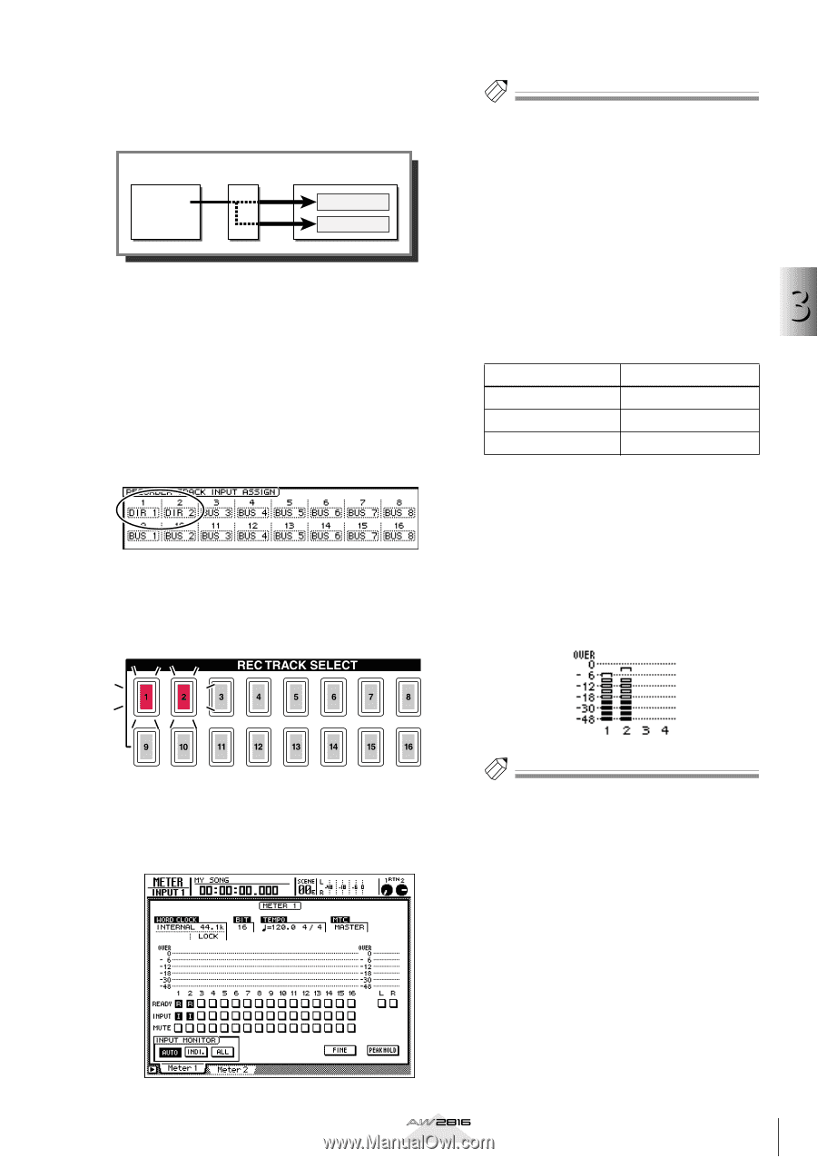
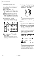
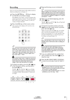
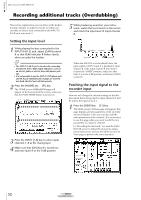
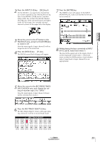
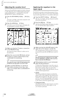
When the AW2816 is in the default state, the outputs of buses 1-8 (BUS 1-BUS 8) are assigned to recorder inputs 1-8/9-16 as shown in the diagram below. Mixer section Buses 1-8 Recorder input patch ×8 ×8 Recorder section Tracks 1-8 Tracks 9-16 4 Move the cursor to the RECORDER TRACK INPUT ASSIGN area. Change the recorder input 1 setting to "DIR 1," and the recorder input 2 setting to "DIR 2." The DIR 1-DIR 8 settings indicate the direct output (with the initial settings, the post-fader input signal) of input channels 1-8. As shown in the diagram below, patching "DIR 1" and "DIR 2" to recorder inputs 1/2 will cause the input signal of input channels 1/2 to be sent directly to tracks 1/ 2. 5 Press the REC TRACK SELECT [1]/[2] keys. The REC TRACK SELECT [1]/[2] keys will begin blinking, and tracks 1/2 will be in record-ready mode. Tip! The METER screen has two pages, Meter 1 and Meter 2, and you can switch between these by using the [F1]/[F2] keys or by repeatedly pressing the [METER] key. The functions of the meter area are the same for both pages. 7 In the INPUT MONITOR area, make sure that the AUTO button is on. The three buttons in the INPUT MONITOR area located in the lower right of the METER screen are used to select the input metering mode (the way in which input metering of each track is switched). When the AUTO button is on, the signal being monitored for record-ready tracks will 3 change automatically depending on the running mode, as shown in the following table. Let's record on the AW2816 Running mode Stopped Playing Recording Monitored signal Track input source Track playback Track input source 8 While playing sounds on the instrument connected to the INPUT 1/2 jacks, check level meters 1/2. The level of the signals input to tracks 1/2 will be displayed in level meters 1/2. (However at this stage, they will not yet be output to the MONITOR OUT jacks/PHONE jack.) If the level meters reach the OVER position, check whether the fader 1/2 (input level of input channels 1/2) settings are appropriate. 6 Press the [METER] key. The METER screen will appear, displaying meters that indicate the input/output levels of tracks 1- 16. Tip! You can use the Quick Rec screen to make the settings of steps 1-6 in a single operation. For details on the Quick Rec function, refer to page 80. Operation section 49
-
 1
1 -
2
-
3
-
4
-
5
-
6
-
7
-
8
-
9
-
10
-
11
-
12
-
13
-
14
-
15
-
16
-
17
-
18
-
19
-
20
-
21
-
22
-
23
-
24
-
25
-
26
-
27
-
28
-
29
-
30
-
31
-
32
-
33
-
34
-
35
-
36
-
37
-
38
-
39
-
40
-
41
-
42
-
43
-
44
-
45
-
46
-
47
-
48
-
49
-
50
-
51
-
 52
52 -
 53
53 -
 54
54 -
 55
55 -
 56
56 -
 57
57 -
 58
58 -
 59
59 -
 60
60 -
 61
61 -
 62
62 -
63
-
64
-
65
-
66
-
67
-
68
-
69
-
70
-
71
-
72
-
73
-
74
-
75
-
76
-
77
-
78
-
79
-
80
-
81
-
82
-
83
-
84
-
85
-
86
-
87
-
88
-
89
-
90
-
91
-
92
-
93
-
94
-
95
-
96
-
97
-
98
-
99
-
100
-
101
-
102
-
103
-
104
-
105
-
106
-
107
-
108
-
109
-
110
-
111
-
112
-
113
-
114
-
115
-
116
-
117
-
118
-
119
-
120
-
121
-
122
-
123
-
124
-
125
-
126
-
127
-
128
-
129
-
130
-
131
-
132
-
133
-
134
-
135
-
136
-
137
-
138
-
139
-
140
-
141
-
142
-
143
-
144
-
145
-
146
-
147
-
148
-
149
-
150
-
151
-
152
-
153
-
154
-
155
-
156
-
157
-
158
-
159
-
160
-
161
-
162
-
163
-
164
-
165
-
166
-
167
-
168
-
169
-
170
-
171
-
172
-
173
-
174
-
175
-
176
-
177
-
178
-
179
-
180
-
181
-
182
-
183
-
184
-
185
-
186
-
187
-
188
-
189
-
190
-
191
-
192
-
193
-
194
-
195
-
196
-
197
-
198
-
199
-
200
-
201
-
202
-
203
-
204
-
205
-
206
-
207
-
208
-
209
-
210
-
211
-
212
-
213
-
214
-
215
-
216
-
217
-
218
-
219
-
220
-
221
-
222
-
223
-
224
-
225
-
226
-
227
-
228
-
229
-
230
-
231
-
232
-
233
-
234
-
235
-
236
-
237
-
238
-
239
-
240
-
241
-
242
-
243
-
244
-
245
-
246
-
247
-
248
-
249
-
250
-
251
-
252
-
253
-
254
-
255
-
256
-
257
-
258
-
259
-
260
-
261
-
262
-
263
-
264
-
265
-
266
-
267
-
268
-
269
-
270
-
271
-
272
-
273
-
274
-
275
-
276
-
277
-
278
-
279
-
280
-
281
-
282
-
283
-
284
-
285
-
286
-
287
-
288
-
289
-
290
-
291
-
292
-
293
-
294
-
295
-
296
-
297
-
298
-
299
-
300
-
301
-
302
-
303
-
304
-
305
-
306
-
307
-
308
-
309
-
310
-
311
-
312
-
313
-
314
-
315
-
316
-
317
-
318
-
319
-
320
-
321
-
322
-
323
-
324
-
325
-
326
-
327
-
328
-
329
-
330
-
331
-
332
-
333
-
334
-
335
-
336
-
337
-
338
-
339
-
340
-
341
-
342
-
343
-
344
-
345
-
346
-
347
-
348
-
349
-
350
-
351
-
352
-
353
-
354
-
355
-
356
-
357
-
358
-
359
-
360
-
361
-
362
-
363
-
364
-
365
-
366
-
367
-
368
-
369
-
370
-
371
-
372
-
373
-
374
-
375
-
376
-
377
-
378
-
379
-
380
-
381
-
382
-
383
-
384
-
385
-
386
-
387
-
388
-
389
-
390
-
391
-
392
-
393
-
394
-
395
-
396
-
397
-
398
-
399
-
400
-
401
-
402
-
403
-
404
-
405
-
406
-
407
-
408
-
409
-
410
-
411
-
412
-
413
-
414
-
415
-
416
-
417
-
418
-
419
-
420
 |
 |