D-Link DGS-3200-16 User Manual - Page 125
Host-Based Network Access Control, 802.1X Settings
 |
UPC - 790069312007
View all D-Link DGS-3200-16 manuals
Add to My Manuals
Save this manual to your list of manuals |
Page 125 highlights
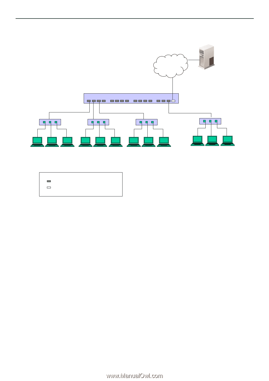
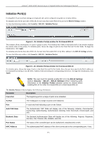
xStack® DGS-3200 Series Layer 2 Gigabit Ethernet Managed Switch Host-Based Network Access Control Ethernet Switch RADIUS Server 802.1X 802.1X 802.1X Client Client Client 802.1X 802.1X 802.1X Client Client Client 802.1X 802.1X 802.1X Client Client Client ... 802.1X 802.1X 802.1X Client Client Client Network access controlled port Network access uncontrolled port Figure 5 - 22. Example of Typical Host-Based Configuration In order to successfully make use of 802.1X in a shared media LAN segment, it would be necessary to create "logical" Ports, one for each attached device that required access to the LAN. The Switch would regard the single physical Port connecting it to the shared media segment as consisting of a number of distinct logical Ports, each logical Port being independently controlled from the point of view of EAPOL exchanges and authorization state. The Switch learns each attached devices' individual MAC addresses, and effectively creates a logical Port that the attached device can then use to communicate with the LAN via the Switch. The 802.1X folder contains seven windows (depending on the current 802.1X) settings: 802.1X Settings, 802.1X User, Initialize Port(s) (Port-based and MAC-based), Reauthenticate Port(s) (Port-based and MAC-based), and Authentic RADIUS Server. 802.1X Settings Users can configure 802.1X authenticator settings. To view the following window, click Security > 802.1X > 802.1X Settings: 112
-
 1
1 -
2
-
3
-
4
-
5
-
6
-
7
-
8
-
9
-
10
-
11
-
12
-
13
-
14
-
15
-
16
-
17
-
18
-
19
-
20
-
21
-
22
-
23
-
24
-
25
-
26
-
27
-
28
-
29
-
30
-
31
-
32
-
33
-
34
-
35
-
36
-
37
-
38
-
39
-
40
-
41
-
42
-
43
-
44
-
45
-
46
-
47
-
48
-
49
-
50
-
51
-
52
-
53
-
54
-
55
-
56
-
57
-
58
-
59
-
60
-
61
-
62
-
63
-
64
-
65
-
66
-
67
-
68
-
69
-
70
-
71
-
72
-
73
-
74
-
75
-
76
-
77
-
78
-
79
-
80
-
81
-
82
-
83
-
84
-
85
-
86
-
87
-
88
-
89
-
90
-
91
-
92
-
93
-
94
-
95
-
96
-
97
-
98
-
99
-
100
-
101
-
102
-
103
-
104
-
105
-
106
-
107
-
108
-
109
-
110
-
111
-
112
-
113
-
114
-
115
-
116
-
117
-
118
-
119
-
 120
120 -
 121
121 -
 122
122 -
 123
123 -
 124
124 -
 125
125 -
 126
126 -
 127
127 -
 128
128 -
 129
129 -
 130
130 -
131
-
132
-
133
-
134
-
135
-
136
-
137
-
138
-
139
-
140
-
141
-
142
-
143
-
144
-
145
-
146
-
147
-
148
-
149
-
150
-
151
-
152
-
153
-
154
-
155
-
156
-
157
-
158
-
159
-
160
-
161
-
162
-
163
-
164
-
165
-
166
-
167
-
168
-
169
-
170
-
171
-
172
-
173
-
174
-
175
-
176
-
177
-
178
-
179
-
180
-
181
-
182
-
183
-
184
-
185
-
186
-
187
-
188
-
189
-
190
-
191
-
192
-
193
-
194
-
195
-
196
-
197
-
198
-
199
-
200
-
201
-
202
-
203
-
204
-
205
-
206
-
207
-
208
-
209
-
210
-
211
-
212
-
213
-
214
-
215
-
216
-
217
-
218
-
219
-
220
-
221
-
222
-
223
-
224
-
225
-
226
-
227
-
228
-
229
-
230
-
231
-
232
-
233
-
234
-
235
-
236
-
237
-
238
-
239
-
240
-
241
-
242
-
243
-
244
-
245
-
246
-
247
-
248
-
249
-
250
-
251
-
252
-
253
-
254
-
255
-
256
-
257
-
258
-
259
-
260
-
261
-
262
-
263
-
264
-
265
-
266
-
267
-
268
-
269
-
270
-
271
-
272
-
273
 |
 |