D-Link DGS-3200-16 User Manual - Page 66
Egress Filter Settings, 802.1Q VLAN, Understanding IEEE 802.1p Priority
 |
UPC - 790069312007
View all D-Link DGS-3200-16 manuals
Add to My Manuals
Save this manual to your list of manuals |
Page 66 highlights
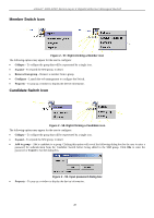
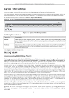
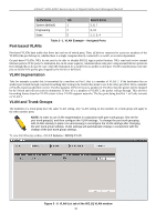
xStack® DGS-3200 Series Layer 2 Gigabit Ethernet Managed Switch Egress Filter Settings Users can configure an egress filter on specific ports for unknown unicast and unregistered multicast packets. The Switch drops all unknown unicast/multicast packets on egress ports when it detects unknown unicast/multicast packets for egress ports. Therefore, a user can select which port is permitted or not permitted to receive unknown unicast/multicast packets. To view the following window, click Layer 2 Features > Egress Filter Settings: Figure 3 - 2. Egress Filter Settings window The following fields can then be set: Parameter Description Unicast Select ports to filter unknown unicast packets. These packets will not be forwarded to those ports. Unselected ports will not filter unknown unicast packets and the packets may be forwarded to those ports. Multicast Select ports to filter unregistered multicast packets. These packets will not be forwarded to those ports. Unselected ports will not filter unregistered multicast packets and the packets may be forwarded to those ports. Click Apply to implement changes made. 802.1Q VLAN Understanding IEEE 802.1p Priority Priority tagging is a function defined by the IEEE 802.1p standard designed to provide a means of managing traffic on a network where many different types of data may be transmitted simultaneously. It is intended to alleviate problems associated with the delivery of time critical data over congested networks. The quality of applications that are dependent on such time critical data, such as video conferencing, can be severely and adversely affected by even very small delays in transmission. Network devices that are in compliance with the IEEE 802.1p standard have the ability to recognize the priority level of data packets. These devices can also assign a priority label or tag to packets. Compliant devices can also strip priority tags from packets. This priority tag determines the packet's degree of expeditiousness and determines the queue to which it will be assigned. Priority tags are given values from 0 to 7 with 0 being assigned to the lowest priority data and 7 assigned to the highest. The highest priority tag 7 is generally only used for data associated with video or audio applications, which are sensitive to even slight delays, or for data from specified end users whose data transmissions warrant special consideration. The Switch allows you to further tailor how priority tagged data packets are handled on your network. Using queues to manage priority tagged data allows you to specify its relative priority to suit the needs of your network. There may be circumstances where it would be advantageous to group two or more differently tagged packets into the same queue. Generally, however, it is recommended that the highest priority queue, Queue 7, be reserved for data packets with a priority value of 7. Packets that have not been given any priority value are placed in Queue 0 and thus given the lowest priority for delivery. Strict mode and weighted round robin system are employed on the Switch to determine the rate at which the queues are emptied of packets. The ratio used for clearing the queues is 4:1. This means that the highest priority queue, Queue 7, will clear 4 packets for every 1 packet cleared from Queue 0. Remember, the priority queue settings on the Switch are for all ports, and all devices connected to the Switch will be affected. This priority queuing system will be especially beneficial if your network employs switches with the capability of assigning priority tags. 53
-
 1
1 -
2
-
3
-
4
-
5
-
6
-
7
-
8
-
9
-
10
-
11
-
12
-
13
-
14
-
15
-
16
-
17
-
18
-
19
-
20
-
21
-
22
-
23
-
24
-
25
-
26
-
27
-
28
-
29
-
30
-
31
-
32
-
33
-
34
-
35
-
36
-
37
-
38
-
39
-
40
-
41
-
42
-
43
-
44
-
45
-
46
-
47
-
48
-
49
-
50
-
51
-
52
-
53
-
54
-
55
-
56
-
57
-
58
-
59
-
60
-
 61
61 -
 62
62 -
 63
63 -
 64
64 -
 65
65 -
 66
66 -
 67
67 -
 68
68 -
 69
69 -
 70
70 -
 71
71 -
72
-
73
-
74
-
75
-
76
-
77
-
78
-
79
-
80
-
81
-
82
-
83
-
84
-
85
-
86
-
87
-
88
-
89
-
90
-
91
-
92
-
93
-
94
-
95
-
96
-
97
-
98
-
99
-
100
-
101
-
102
-
103
-
104
-
105
-
106
-
107
-
108
-
109
-
110
-
111
-
112
-
113
-
114
-
115
-
116
-
117
-
118
-
119
-
120
-
121
-
122
-
123
-
124
-
125
-
126
-
127
-
128
-
129
-
130
-
131
-
132
-
133
-
134
-
135
-
136
-
137
-
138
-
139
-
140
-
141
-
142
-
143
-
144
-
145
-
146
-
147
-
148
-
149
-
150
-
151
-
152
-
153
-
154
-
155
-
156
-
157
-
158
-
159
-
160
-
161
-
162
-
163
-
164
-
165
-
166
-
167
-
168
-
169
-
170
-
171
-
172
-
173
-
174
-
175
-
176
-
177
-
178
-
179
-
180
-
181
-
182
-
183
-
184
-
185
-
186
-
187
-
188
-
189
-
190
-
191
-
192
-
193
-
194
-
195
-
196
-
197
-
198
-
199
-
200
-
201
-
202
-
203
-
204
-
205
-
206
-
207
-
208
-
209
-
210
-
211
-
212
-
213
-
214
-
215
-
216
-
217
-
218
-
219
-
220
-
221
-
222
-
223
-
224
-
225
-
226
-
227
-
228
-
229
-
230
-
231
-
232
-
233
-
234
-
235
-
236
-
237
-
238
-
239
-
240
-
241
-
242
-
243
-
244
-
245
-
246
-
247
-
248
-
249
-
250
-
251
-
252
-
253
-
254
-
255
-
256
-
257
-
258
-
259
-
260
-
261
-
262
-
263
-
264
-
265
-
266
-
267
-
268
-
269
-
270
-
271
-
272
-
273
 |
 |