D-Link DGS-3200-16 User Manual - Page 178
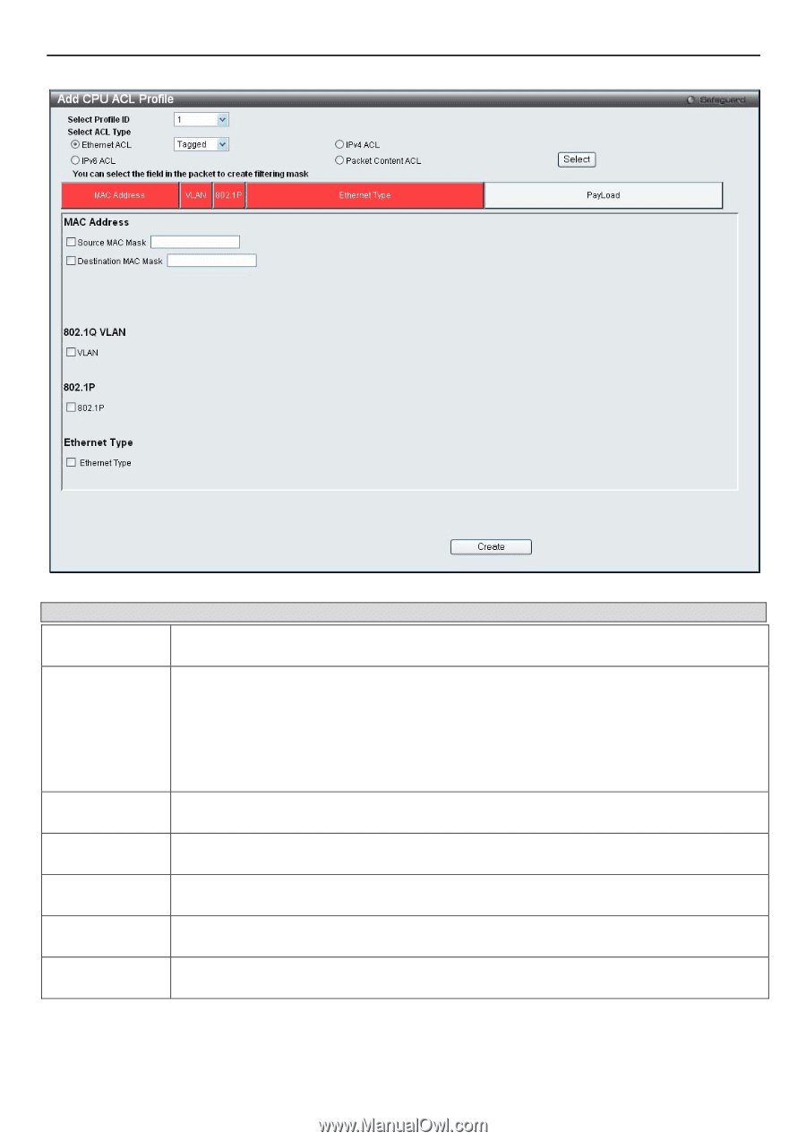
Add CPU ACL Profile window for Ethernet
 |
UPC - 790069312007
View all D-Link DGS-3200-16 manuals
Add to My Manuals
Save this manual to your list of manuals |
Page 178 highlights
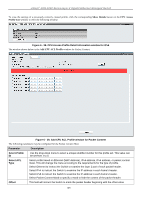
xStack® DGS-3200 Series Layer 2 Gigabit Ethernet Managed Switch Parameter Figure 6 - 23. Add CPU ACL Profile window for Ethernet Description Select Profile ID (1-5) Select ACL Type Source MAC Mask Destination MAC Mask 802.1Q VLAN 802.1p Ethernet Type Use the drop-down menu to select a unique identifier number for this profile set. This value can be set from 1 to 5. Select profile based on Ethernet (MAC Address), IPv4 address, IPv6 address, or packet content mask. This will change the window according to the requirements for the type of profile. Select Ethernet to instruct the Switch to examine the layer 2 part of each packet header. Select IPv4 to instruct the Switch to examine the IP address in each frame's header. Select IPv6 to instruct the Switch to examine the IP address in each frame's header. Select Packet Content Mask to specify a mask to hide the content of the packet header. Enter a MAC address mask for the source MAC address. Enter a MAC address mask for the destination MAC address. Selecting this option instructs the Switch to examine the VLAN identifier of each packet header and use this as the full or partial criterion for forwarding. Selecting this option instructs the Switch to specify that the access profile will apply only to packets with this 802.1p priority value. Selecting this option instructs the Switch to examine the Ethernet type value in each frame's header. Click Apply to set this entry in the Switch's memory. 165
-
 1
1 -
2
-
3
-
4
-
5
-
6
-
7
-
8
-
9
-
10
-
11
-
12
-
13
-
14
-
15
-
16
-
17
-
18
-
19
-
20
-
21
-
22
-
23
-
24
-
25
-
26
-
27
-
28
-
29
-
30
-
31
-
32
-
33
-
34
-
35
-
36
-
37
-
38
-
39
-
40
-
41
-
42
-
43
-
44
-
45
-
46
-
47
-
48
-
49
-
50
-
51
-
52
-
53
-
54
-
55
-
56
-
57
-
58
-
59
-
60
-
61
-
62
-
63
-
64
-
65
-
66
-
67
-
68
-
69
-
70
-
71
-
72
-
73
-
74
-
75
-
76
-
77
-
78
-
79
-
80
-
81
-
82
-
83
-
84
-
85
-
86
-
87
-
88
-
89
-
90
-
91
-
92
-
93
-
94
-
95
-
96
-
97
-
98
-
99
-
100
-
101
-
102
-
103
-
104
-
105
-
106
-
107
-
108
-
109
-
110
-
111
-
112
-
113
-
114
-
115
-
116
-
117
-
118
-
119
-
120
-
121
-
122
-
123
-
124
-
125
-
126
-
127
-
128
-
129
-
130
-
131
-
132
-
133
-
134
-
135
-
136
-
137
-
138
-
139
-
140
-
141
-
142
-
143
-
144
-
145
-
146
-
147
-
148
-
149
-
150
-
151
-
152
-
153
-
154
-
155
-
156
-
157
-
158
-
159
-
160
-
161
-
162
-
163
-
164
-
165
-
166
-
167
-
168
-
169
-
170
-
171
-
172
-
 173
173 -
 174
174 -
 175
175 -
 176
176 -
 177
177 -
 178
178 -
 179
179 -
 180
180 -
 181
181 -
 182
182 -
 183
183 -
184
-
185
-
186
-
187
-
188
-
189
-
190
-
191
-
192
-
193
-
194
-
195
-
196
-
197
-
198
-
199
-
200
-
201
-
202
-
203
-
204
-
205
-
206
-
207
-
208
-
209
-
210
-
211
-
212
-
213
-
214
-
215
-
216
-
217
-
218
-
219
-
220
-
221
-
222
-
223
-
224
-
225
-
226
-
227
-
228
-
229
-
230
-
231
-
232
-
233
-
234
-
235
-
236
-
237
-
238
-
239
-
240
-
241
-
242
-
243
-
244
-
245
-
246
-
247
-
248
-
249
-
250
-
251
-
252
-
253
-
254
-
255
-
256
-
257
-
258
-
259
-
260
-
261
-
262
-
263
-
264
-
265
-
266
-
267
-
268
-
269
-
270
-
271
-
272
-
273
 |
 |