D-Link DGS-3200-16 User Manual - Page 93
Port Transition States, Edge Port, P2P Port, 802.1D-1998/802.1D-2004/802.1Q-2005 Compatibility
 |
UPC - 790069312007
View all D-Link DGS-3200-16 manuals
Add to My Manuals
Save this manual to your list of manuals |
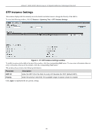
Page 93 highlights
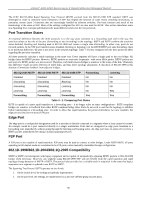
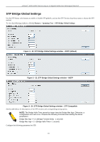
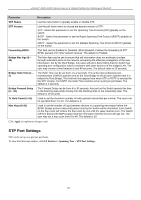
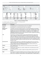
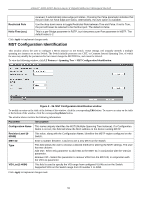
xStack® DGS-3200 Series Layer 2 Gigabit Ethernet Managed Switch The IEEE 802.1D-2004 Rapid Spanning Tree Protocol (RSTP) evolved from the 802.1D-1998 STP standard. RSTP was developed in order to overcome some limitations of STP that impede the function of some recent switching innovations, in particular, certain Layer 3 functions that are increasingly handled by Ethernet switches. The basic function and much of the terminology is the same as STP. Most of the settings configured for STP are also used for RSTP. This section introduces some new Spanning Tree concepts and illustrates the main differences between the two protocols. Port Transition States An essential difference between the three protocols is in the way ports transition to a forwarding state and in the way this transition relates to the role of the port (forwarding or not forwarding) in the topology. MSTP and RSTP combine the transition states disabled, blocking and listening used in 802.1D-1998 and creates a single state Discarding. In either case, ports do not forward packets. In the STP port transition states disabled, blocking or listening or in the RSTP/MSTP port state discarding, there is no functional difference, the port is not active in the network topology. Table 7-3 below compares how the three protocols differ regarding the port state transition. All three protocols calculate a stable topology in the same way. Every segment will have a single path to the root bridge. All bridges listen for BPDU packets. However, BPDU packets are sent more frequently - with every Hello packet. BPDU packets are sent even if a BPDU packet was not received. Therefore, each link between bridges is sensitive to the status of the link. Ultimately this difference results in faster detection of failed links, and thus faster topology adjustment. A drawback of 802.1D-1998 is this absence of immediate feedback from adjacent bridges. 802.1Q-2005 MSTP 802.1D-2004 RSTP Disabled Disabled Discarding Discarding Discarding Discarding Learning Learning Forwarding Forwarding 802.1D-1998 STP Disabled Blocking Listening Learning Forwarding Forwarding No No No No Yes Learning No No No Yes Yes Table 3 - 2. Comparing Port States RSTP is capable of a more rapid transition to a forwarding state - it no longer relies on timer configurations - RSTP compliant bridges are sensitive to feedback from other RSTP compliant bridge links. Ports do not need to wait for the topology to stabilize before transitioning to a forwarding state. In order to allow this rapid transition, the protocol introduces two new variables: the edge port and the point-to-point (P2P) port. Edge Port The edge port is a configurable designation used for a port that is directly connected to a segment where a loop cannot be created. An example would be a port connected directly to a single workstation. Ports that are designated as edge ports transition to a forwarding state immediately without going through the listening and learning states. An edge port loses its status if it receives a BPDU packet, immediately becoming a normal spanning tree port. P2P Port A P2P port is also capable of rapid transition. P2P ports may be used to connect to other bridges. Under RSTP/MSTP, all ports operating in full-duplex mode are considered to be P2P ports, unless manually overridden through configuration. 802.1D-1998/802.1D-2004/802.1Q-2005 Compatibility MSTP or RSTP can interoperate with legacy equipment and is capable of automatically adjusting BPDU packets to 802.1D-1998 format when necessary. However, any segment using 802.1D-1998 STP will not benefit from the rapid transition and rapid topology change detection of MSTP or RSTP. The protocol also provides for a variable used for migration in the event that legacy equipment on a segment is updated to use RSTP or MSTP. The Spanning Tree Protocol (STP) operates on two levels: 1. On the switch level, the settings are globally implemented. 2. On the port level, the settings are implemented on a per user-defined group of ports basis. 80
-
 1
1 -
2
-
3
-
4
-
5
-
6
-
7
-
8
-
9
-
10
-
11
-
12
-
13
-
14
-
15
-
16
-
17
-
18
-
19
-
20
-
21
-
22
-
23
-
24
-
25
-
26
-
27
-
28
-
29
-
30
-
31
-
32
-
33
-
34
-
35
-
36
-
37
-
38
-
39
-
40
-
41
-
42
-
43
-
44
-
45
-
46
-
47
-
48
-
49
-
50
-
51
-
52
-
53
-
54
-
55
-
56
-
57
-
58
-
59
-
60
-
61
-
62
-
63
-
64
-
65
-
66
-
67
-
68
-
69
-
70
-
71
-
72
-
73
-
74
-
75
-
76
-
77
-
78
-
79
-
80
-
81
-
82
-
83
-
84
-
85
-
86
-
87
-
 88
88 -
 89
89 -
 90
90 -
 91
91 -
 92
92 -
 93
93 -
 94
94 -
 95
95 -
 96
96 -
 97
97 -
 98
98 -
99
-
100
-
101
-
102
-
103
-
104
-
105
-
106
-
107
-
108
-
109
-
110
-
111
-
112
-
113
-
114
-
115
-
116
-
117
-
118
-
119
-
120
-
121
-
122
-
123
-
124
-
125
-
126
-
127
-
128
-
129
-
130
-
131
-
132
-
133
-
134
-
135
-
136
-
137
-
138
-
139
-
140
-
141
-
142
-
143
-
144
-
145
-
146
-
147
-
148
-
149
-
150
-
151
-
152
-
153
-
154
-
155
-
156
-
157
-
158
-
159
-
160
-
161
-
162
-
163
-
164
-
165
-
166
-
167
-
168
-
169
-
170
-
171
-
172
-
173
-
174
-
175
-
176
-
177
-
178
-
179
-
180
-
181
-
182
-
183
-
184
-
185
-
186
-
187
-
188
-
189
-
190
-
191
-
192
-
193
-
194
-
195
-
196
-
197
-
198
-
199
-
200
-
201
-
202
-
203
-
204
-
205
-
206
-
207
-
208
-
209
-
210
-
211
-
212
-
213
-
214
-
215
-
216
-
217
-
218
-
219
-
220
-
221
-
222
-
223
-
224
-
225
-
226
-
227
-
228
-
229
-
230
-
231
-
232
-
233
-
234
-
235
-
236
-
237
-
238
-
239
-
240
-
241
-
242
-
243
-
244
-
245
-
246
-
247
-
248
-
249
-
250
-
251
-
252
-
253
-
254
-
255
-
256
-
257
-
258
-
259
-
260
-
261
-
262
-
263
-
264
-
265
-
266
-
267
-
268
-
269
-
270
-
271
-
272
-
273
 |
 |