D-Link DGS-3200-16 User Manual - Page 170
Access Rule Detail Information window for Ethernet
 |
UPC - 790069312007
View all D-Link DGS-3200-16 manuals
Add to My Manuals
Save this manual to your list of manuals |
Page 170 highlights
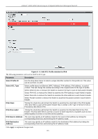
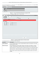
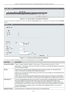
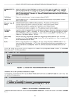
xStack® DGS-3200 Series Layer 2 Gigabit Ethernet Managed Switch Replace DSCP (063) Select this option to instruct the Switch to replace the DSCP value (in a packet that meets the selected criteria) with the value entered in the adjacent field. When an ACL rule is added to change both the priority and DSCP of an IPv4 packet, only one of them can be modified due to a chip limitation. Currently the priority is changed when both the priority and DSCP are set to be modified. VLAN Name Allows the entry of a name for a previously configured VLAN. 802.1p (0-7) Ethernet Type (0FFFF) Rx Rate (1156249) Enter a value from 0 to 7 to specify that the access profile will apply only to packets with this 802.1p priority value. Selected profile based on Ethernet (MAC Address), IP address or IPv6 address Ethernet instructs the Switch to examine the layer 2 part of each packet header. IP instructs the Switch to examine the IP address in each frame's header. IPv6 instructs the Switch to examine the IPv6 address in each frame's header. Use this to limit Rx bandwidth for the profile being configured. This rate is implemented using the following equation: 1 value = 64kbit/sec. (ex. If the user selects an Rx rate of 10 then the ingress rate is 640kbit/sec.) The user many select a value between 1 and 156249 or tick the No Limit check box. The default setting is No Limit. Time Range Name Tick the check box and enter the name of the Time Range settings that has been previously configured in the Time Range Settings window. This will set specific times when this access rule will be implemented on the Switch. Ports When a range of ports is to be configured, the Auto Assign check box MUST be ticked in the Access ID field of this window. If not, the user will be presented with an error message and the access rule will not be configured. Ticking the All Ports check box will denote all ports on the Switch. To view the settings of a previously correctly configured rule, click the corresponding Show Details button on the Access Rule List window to view the following window: Figure 6 - 12. Access Rule Detail Information window for Ethernet To establish the rule for a previously created Access Profile: To configure the Access Rules for IPv4, open the Access Profile List window and click Add/View Rules for an IPv4 entry. This will open the following window: Figure 6 - 13. Access Rule List window for IPv4 To remove a previously created rule, click the corresponding Delete Rules button. To add a new Access Rule, click the Add Rule button: 157
-
 1
1 -
2
-
3
-
4
-
5
-
6
-
7
-
8
-
9
-
10
-
11
-
12
-
13
-
14
-
15
-
16
-
17
-
18
-
19
-
20
-
21
-
22
-
23
-
24
-
25
-
26
-
27
-
28
-
29
-
30
-
31
-
32
-
33
-
34
-
35
-
36
-
37
-
38
-
39
-
40
-
41
-
42
-
43
-
44
-
45
-
46
-
47
-
48
-
49
-
50
-
51
-
52
-
53
-
54
-
55
-
56
-
57
-
58
-
59
-
60
-
61
-
62
-
63
-
64
-
65
-
66
-
67
-
68
-
69
-
70
-
71
-
72
-
73
-
74
-
75
-
76
-
77
-
78
-
79
-
80
-
81
-
82
-
83
-
84
-
85
-
86
-
87
-
88
-
89
-
90
-
91
-
92
-
93
-
94
-
95
-
96
-
97
-
98
-
99
-
100
-
101
-
102
-
103
-
104
-
105
-
106
-
107
-
108
-
109
-
110
-
111
-
112
-
113
-
114
-
115
-
116
-
117
-
118
-
119
-
120
-
121
-
122
-
123
-
124
-
125
-
126
-
127
-
128
-
129
-
130
-
131
-
132
-
133
-
134
-
135
-
136
-
137
-
138
-
139
-
140
-
141
-
142
-
143
-
144
-
145
-
146
-
147
-
148
-
149
-
150
-
151
-
152
-
153
-
154
-
155
-
156
-
157
-
158
-
159
-
160
-
161
-
162
-
163
-
164
-
 165
165 -
 166
166 -
 167
167 -
 168
168 -
 169
169 -
 170
170 -
 171
171 -
 172
172 -
 173
173 -
 174
174 -
 175
175 -
176
-
177
-
178
-
179
-
180
-
181
-
182
-
183
-
184
-
185
-
186
-
187
-
188
-
189
-
190
-
191
-
192
-
193
-
194
-
195
-
196
-
197
-
198
-
199
-
200
-
201
-
202
-
203
-
204
-
205
-
206
-
207
-
208
-
209
-
210
-
211
-
212
-
213
-
214
-
215
-
216
-
217
-
218
-
219
-
220
-
221
-
222
-
223
-
224
-
225
-
226
-
227
-
228
-
229
-
230
-
231
-
232
-
233
-
234
-
235
-
236
-
237
-
238
-
239
-
240
-
241
-
242
-
243
-
244
-
245
-
246
-
247
-
248
-
249
-
250
-
251
-
252
-
253
-
254
-
255
-
256
-
257
-
258
-
259
-
260
-
261
-
262
-
263
-
264
-
265
-
266
-
267
-
268
-
269
-
270
-
271
-
272
-
273
 |
 |