D-Link DGS-3200-16 User Manual - Page 176
CPU Access Profile List, Time Range, Settings, Ports - 163
 |
UPC - 790069312007
View all D-Link DGS-3200-16 manuals
Add to My Manuals
Save this manual to your list of manuals |
Page 176 highlights
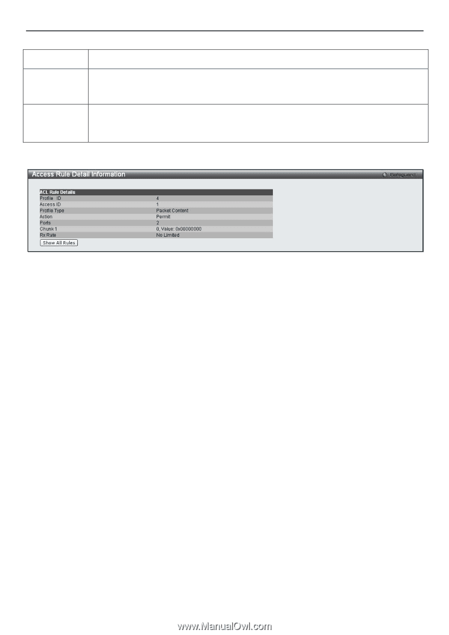
xStack® DGS-3200 Series Layer 2 Gigabit Ethernet Managed Switch 156249) rate is 640kbit/sec.) The user many select a value between 1 and 156249 or tick the No Limit check box. The default setting is No Limit. Time Range Name Tick the check box and enter the name of the Time Range settings that has been previously configured in the Time Range Settings window. This will set specific times when this access rule will be implemented on the Switch. Ports When a range of ports is to be configured, the Auto Assign check box MUST be ticked in the Access ID field of this window. If not, the user will be presented with an error message and the access rule will not be configured. Ticking the All Ports check box will denote all ports on the Switch. To view the settings of a previously correctly configured rule, click the corresponding Show Details button on the Access Rule List window to view the following window: Figure 6 - 21. Access Rule Detail Information window for Packet Content CPU Access Profile List Due to a chipset limitation and needed extra switch security, the Switch incorporates CPU Interface filtering. This added feature increases the running security of the Switch by enabling the user to create a list of access rules for packets destined for the Switch's CPU interface. Employed similarly to the Access Profile feature previously mentioned, CPU interface filtering examines Ethernet, IP and Packet Content Mask packet headers destined for the CPU and will either forward them or filter them, based on the user's implementation. As an added feature for the CPU Filtering, the Switch allows the CPU filtering mechanism to be enabled or disabled globally, permitting the user to create various lists of rules without immediately enabling them. Creating an access profile for the CPU is divided into two basic parts. The first is to specify which part or parts of a frame the Switch will examine, such as the MAC source address or the IP destination address. The second part is entering the criteria the Switch will use to determine what to do with the frame. The entire process is described below. Users may globally enable or disable the CPU Interface Filtering State mechanism by using the radio buttons to change the running state. Choose Enabled to enable CPU packets to be scrutinized by the Switch and Disabled to disallow this scrutiny. To view the following window, click ACL > CPU Access Profile List: 163
-
 1
1 -
2
-
3
-
4
-
5
-
6
-
7
-
8
-
9
-
10
-
11
-
12
-
13
-
14
-
15
-
16
-
17
-
18
-
19
-
20
-
21
-
22
-
23
-
24
-
25
-
26
-
27
-
28
-
29
-
30
-
31
-
32
-
33
-
34
-
35
-
36
-
37
-
38
-
39
-
40
-
41
-
42
-
43
-
44
-
45
-
46
-
47
-
48
-
49
-
50
-
51
-
52
-
53
-
54
-
55
-
56
-
57
-
58
-
59
-
60
-
61
-
62
-
63
-
64
-
65
-
66
-
67
-
68
-
69
-
70
-
71
-
72
-
73
-
74
-
75
-
76
-
77
-
78
-
79
-
80
-
81
-
82
-
83
-
84
-
85
-
86
-
87
-
88
-
89
-
90
-
91
-
92
-
93
-
94
-
95
-
96
-
97
-
98
-
99
-
100
-
101
-
102
-
103
-
104
-
105
-
106
-
107
-
108
-
109
-
110
-
111
-
112
-
113
-
114
-
115
-
116
-
117
-
118
-
119
-
120
-
121
-
122
-
123
-
124
-
125
-
126
-
127
-
128
-
129
-
130
-
131
-
132
-
133
-
134
-
135
-
136
-
137
-
138
-
139
-
140
-
141
-
142
-
143
-
144
-
145
-
146
-
147
-
148
-
149
-
150
-
151
-
152
-
153
-
154
-
155
-
156
-
157
-
158
-
159
-
160
-
161
-
162
-
163
-
164
-
165
-
166
-
167
-
168
-
169
-
170
-
 171
171 -
 172
172 -
 173
173 -
 174
174 -
 175
175 -
 176
176 -
 177
177 -
 178
178 -
 179
179 -
 180
180 -
 181
181 -
182
-
183
-
184
-
185
-
186
-
187
-
188
-
189
-
190
-
191
-
192
-
193
-
194
-
195
-
196
-
197
-
198
-
199
-
200
-
201
-
202
-
203
-
204
-
205
-
206
-
207
-
208
-
209
-
210
-
211
-
212
-
213
-
214
-
215
-
216
-
217
-
218
-
219
-
220
-
221
-
222
-
223
-
224
-
225
-
226
-
227
-
228
-
229
-
230
-
231
-
232
-
233
-
234
-
235
-
236
-
237
-
238
-
239
-
240
-
241
-
242
-
243
-
244
-
245
-
246
-
247
-
248
-
249
-
250
-
251
-
252
-
253
-
254
-
255
-
256
-
257
-
258
-
259
-
260
-
261
-
262
-
263
-
264
-
265
-
266
-
267
-
268
-
269
-
270
-
271
-
272
-
273
 |
 |