D-Link DGS-3620-28TC-SI Product Manual - Page 102
MST Configuration Identification, L2 Features > Spanning Tree > MST Configuration Identification
 |
View all D-Link DGS-3620-28TC-SI manuals
Add to My Manuals
Save this manual to your list of manuals |
Page 102 highlights
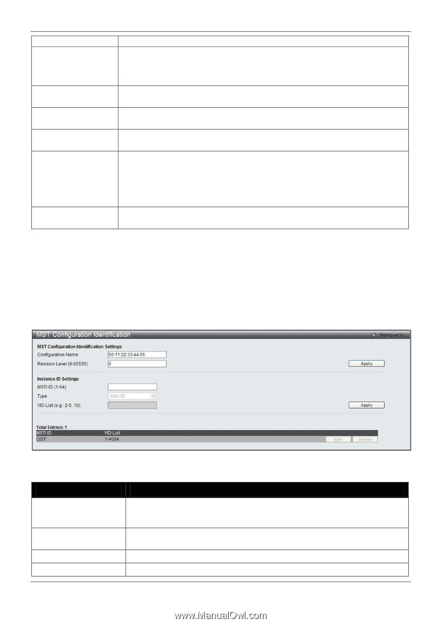
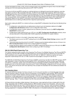
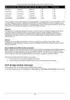
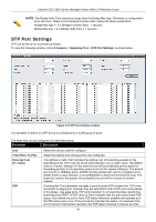
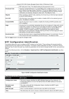
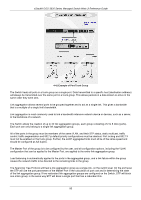
xStack® DGS-3620 Series Managed Switch Web UI Reference Guide P2P value were False. The default setting for this parameter is Auto. Restricted TCN Topology Change Notification is a simple BPDU that a bridge sends out to its root port to signal a topology change. Restricted TCN can be toggled between True and False. If set to True, this stops the port from propagating received topology change notifications and topology changes to other ports. The default is False. Migrate When operating in RSTP mode, selecting Yes forces the port that has been selected to transmit RSTP BPDUs. Port STP This drop-down menu allows you to enable or disable STP for the selected group of ports. The default is Enabled. Forward BPDU Use the drop-down menu to enable or disable the flooding of BPDU packets when STP is disabled. Edge Choosing the True parameter designates the port as an edge port. Edge ports cannot create loops, however an edge port can lose edge port status if a topology change creates a potential for a loop. An edge port normally should not receive BPDU packets. If a BPDU packet is received, it automatically loses edge port status. Choosing the False parameter indicates that the port does not have edge port status. Alternatively, the Auto option is available. Restricted Role Use the drop-down menu to toggle Restricted Role between True and False. If set to True, the port will never be selected to be the Root port. The default is False. Click the Apply button to accept the changes made. MST Configuration Identification This window allows the user to configure a MSTI instance on the Switch. These settings will uniquely identify a multiple spanning tree instance set on the Switch. The Switch initially possesses one CIST, or Common Internal Spanning Tree, of which the user may modify the parameters for but cannot change the MSTI ID for, and cannot be deleted. To view the following window, click L2 Features > Spanning Tree > MST Configuration Identification, as show below: Figure 4-38 MST Configuration Identification window The fields that can be configured are described below: Parameter Description Configuration Name Revision Level (0-65535) MSTI ID (1-64) Type This name uniquely identifies the MSTI (Multiple Spanning Tree Instance). If a Configuration Name is not set, this field will show the MAC address to the device running MSTP. This value, along with the Configuration Name, identifies the MSTP region configured on the Switch. Enter a number between 1 and 64 to set a new MSTI on the Switch. This field allows the user to choose a desired method for altering the MSTI settings. 92
-
 1
1 -
2
-
3
-
4
-
5
-
6
-
7
-
8
-
9
-
10
-
11
-
12
-
13
-
14
-
15
-
16
-
17
-
18
-
19
-
20
-
21
-
22
-
23
-
24
-
25
-
26
-
27
-
28
-
29
-
30
-
31
-
32
-
33
-
34
-
35
-
36
-
37
-
38
-
39
-
40
-
41
-
42
-
43
-
44
-
45
-
46
-
47
-
48
-
49
-
50
-
51
-
52
-
53
-
54
-
55
-
56
-
57
-
58
-
59
-
60
-
61
-
62
-
63
-
64
-
65
-
66
-
67
-
68
-
69
-
70
-
71
-
72
-
73
-
74
-
75
-
76
-
77
-
78
-
79
-
80
-
81
-
82
-
83
-
84
-
85
-
86
-
87
-
88
-
89
-
90
-
91
-
92
-
93
-
94
-
95
-
96
-
 97
97 -
 98
98 -
 99
99 -
 100
100 -
 101
101 -
 102
102 -
 103
103 -
 104
104 -
 105
105 -
 106
106 -
 107
107 -
108
-
109
-
110
-
111
-
112
-
113
-
114
-
115
-
116
-
117
-
118
-
119
-
120
-
121
-
122
-
123
-
124
-
125
-
126
-
127
-
128
-
129
-
130
-
131
-
132
-
133
-
134
-
135
-
136
-
137
-
138
-
139
-
140
-
141
-
142
-
143
-
144
-
145
-
146
-
147
-
148
-
149
-
150
-
151
-
152
-
153
-
154
-
155
-
156
-
157
-
158
-
159
-
160
-
161
-
162
-
163
-
164
-
165
-
166
-
167
-
168
-
169
-
170
-
171
-
172
-
173
-
174
-
175
-
176
-
177
-
178
-
179
-
180
-
181
-
182
-
183
-
184
-
185
-
186
-
187
-
188
-
189
-
190
-
191
-
192
-
193
-
194
-
195
-
196
-
197
-
198
-
199
-
200
-
201
-
202
-
203
-
204
-
205
-
206
-
207
-
208
-
209
-
210
-
211
-
212
-
213
-
214
-
215
-
216
-
217
-
218
-
219
-
220
-
221
-
222
-
223
-
224
-
225
-
226
-
227
-
228
-
229
-
230
-
231
-
232
-
233
-
234
-
235
-
236
-
237
-
238
-
239
-
240
-
241
-
242
-
243
-
244
-
245
-
246
-
247
-
248
-
249
-
250
-
251
-
252
-
253
-
254
-
255
-
256
-
257
-
258
-
259
-
260
-
261
-
262
-
263
-
264
-
265
-
266
-
267
-
268
-
269
-
270
-
271
-
272
-
273
-
274
-
275
-
276
-
277
-
278
-
279
-
280
-
281
-
282
-
283
-
284
-
285
-
286
-
287
-
288
-
289
-
290
-
291
-
292
-
293
-
294
-
295
-
296
-
297
-
298
-
299
-
300
-
301
-
302
-
303
-
304
-
305
-
306
-
307
-
308
-
309
-
310
-
311
-
312
-
313
-
314
-
315
-
316
-
317
-
318
-
319
-
320
-
321
-
322
-
323
-
324
-
325
-
326
-
327
-
328
-
329
-
330
-
331
-
332
-
333
-
334
-
335
-
336
-
337
-
338
-
339
-
340
-
341
-
342
-
343
-
344
-
345
-
346
-
347
-
348
-
349
-
350
-
351
-
352
-
353
-
354
-
355
-
356
-
357
-
358
-
359
-
360
-
361
-
362
-
363
-
364
-
365
-
366
-
367
-
368
-
369
-
370
-
371
-
372
-
373
-
374
-
375
-
376
-
377
-
378
-
379
-
380
-
381
-
382
-
383
-
384
-
385
-
386
-
387
-
388
-
389
-
390
-
391
-
392
-
393
-
394
-
395
-
396
-
397
-
398
-
399
-
400
-
401
-
402
-
403
-
404
-
405
-
406
-
407
-
408
-
409
-
410
-
411
-
412
-
413
-
414
-
415
-
416
-
417
-
418
-
419
-
420
-
421
-
422
-
423
-
424
-
425
-
426
-
427
-
428
-
429
-
430
-
431
-
432
-
433
-
434
-
435
-
436
-
437
-
438
-
439
-
440
-
441
-
442
-
443
-
444
-
445
-
446
-
447
-
448
-
449
-
450
-
451
-
452
-
453
-
454
-
455
-
456
-
457
-
458
-
459
-
460
-
461
-
462
-
463
-
464
-
465
-
466
-
467
-
468
-
469
-
470
-
471
-
472
-
473
-
474
-
475
-
476
-
477
-
478
-
479
-
480
-
481
-
482
-
483
-
484
-
485
-
486
-
487
-
488
-
489
-
490
-
491
-
492
-
493
-
494
-
495
-
496
-
497
-
498
-
499
-
500
-
501
-
502
 |
 |