Intel S7000FC4UR Product Guide - Page 100
Remove Memory Board DIMM Cover, Memory Population Rules
 |
UPC - 735858194259
View all Intel S7000FC4UR manuals
Add to My Manuals
Save this manual to your list of manuals |
Page 100 highlights
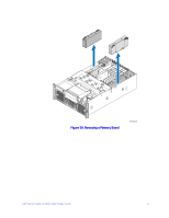
A AF002411 Figure 44. Remove Memory Board DIMM Cover 5. Open the plastic levers on each end of the DIMM socket(s). Remove the DIMM from its antistatic container. Hold the DIMM only by the edges. Do not touch the components or gold edge connectors. 6. Install DIMMs in the correct order. See "Memory Population Rules" on page 79. 7. Position the DIMM above the socket. Align the notch on the bottom edge of the DIMM with the key in the DIMM socket. 8. Insert the bottom edge of the DIMM into the socket. 9. Push down on the top edge of the DIMM. The levers at each end of the DIMM socket will close. Make sure the levers close securely. 82 Intel® Server System S7000FC4UR Product Guide
-
 1
1 -
2
-
3
-
4
-
5
-
6
-
7
-
8
-
9
-
10
-
11
-
12
-
13
-
14
-
15
-
16
-
17
-
18
-
19
-
20
-
21
-
22
-
23
-
24
-
25
-
26
-
27
-
28
-
29
-
30
-
31
-
32
-
33
-
34
-
35
-
36
-
37
-
38
-
39
-
40
-
41
-
42
-
43
-
44
-
45
-
46
-
47
-
48
-
49
-
50
-
51
-
52
-
53
-
54
-
55
-
56
-
57
-
58
-
59
-
60
-
61
-
62
-
63
-
64
-
65
-
66
-
67
-
68
-
69
-
70
-
71
-
72
-
73
-
74
-
75
-
76
-
77
-
78
-
79
-
80
-
81
-
82
-
83
-
84
-
85
-
86
-
87
-
88
-
89
-
90
-
91
-
92
-
93
-
94
-
 95
95 -
 96
96 -
 97
97 -
 98
98 -
 99
99 -
 100
100 -
 101
101 -
 102
102 -
 103
103 -
 104
104 -
 105
105 -
106
-
107
-
108
-
109
-
110
-
111
-
112
-
113
-
114
-
115
-
116
-
117
-
118
-
119
-
120
-
121
-
122
-
123
-
124
-
125
-
126
-
127
-
128
-
129
-
130
-
131
-
132
-
133
-
134
-
135
-
136
-
137
-
138
-
139
-
140
-
141
-
142
-
143
-
144
-
145
-
146
-
147
-
148
-
149
-
150
-
151
-
152
-
153
-
154
-
155
-
156
-
157
-
158
-
159
-
160
-
161
-
162
-
163
-
164
-
165
-
166
-
167
-
168
-
169
-
170
-
171
-
172
-
173
-
174
-
175
-
176
-
177
-
178
-
179
-
180
-
181
-
182
-
183
-
184
-
185
-
186
-
187
-
188
-
189
-
190
-
191
-
192
-
193
-
194
-
195
-
196
-
197
-
198
-
199
-
200
-
201
-
202
-
203
-
204
-
205
-
206
-
207
-
208
-
209
-
210
-
211
-
212
-
213
-
214
-
215
-
216
-
217
-
218
-
219
-
220
-
221
-
222
-
223
-
224
-
225
-
226
-
227
-
228
-
229
-
230
-
231
-
232
 |
 |

82
Intel® Server System S7000FC4UR Product Guide
Figure 44. Remove Memory Board DIMM Cover
5.
Open the plastic levers on each end of the DIMM socket(s). Remove the DIMM
from its antistatic container. Hold the DIMM only by the edges. Do not touch the
components or gold edge connectors.
6.
Install DIMMs in the correct order. See
“Memory Population Rules” on page 79
.
7.
Position the DIMM above the socket. Align the notch on the bottom edge of the
DIMM with the key in the DIMM socket.
8.
Insert the bottom edge of the DIMM into the socket.
9.
Push down on the top edge of the DIMM. The levers at each end of the DIMM
socket will close. Make sure the levers close securely.
AF002411
A