Intel S7000FC4UR Product Guide - Page 92
Removing a Non-hot-swap PCI Card, Operating System Interface
 |
UPC - 735858194259
View all Intel S7000FC4UR manuals
Add to My Manuals
Save this manual to your list of manuals |
Page 92 highlights
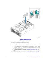
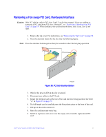
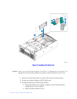
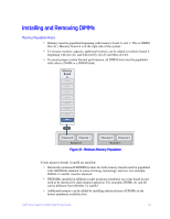
If using the hardware hot-plug interface: ✧ Press the attention button for the slot. If you need to abort the hot-plug operation, press the attention button again within five seconds. ✧ Wait for power LED to turn on. Note: For either the operating system interface or the hardware hot-plug interface, if the attention LED is blinking, a power fault has occurred. You may need to remove the adapter, wait for the LED to turn off, and re-start the hot insertion. 12. Install the top cover. For instructions, see "Installing the Top Cover" on page 59. Removing a Non-hot-swap PCI Card PCI cards in slots 1 and 2 can be hot-swapped. If you want to hot-swap a card in one of these slots, see "Removing a Hot-swap PCI Card, Operating System Interface" on page 69 or "Removing a Hot-swap PCI Card, Hardware Interface" on page 71. Caution: AC power must be removed from the system before servicing a non-hot-swap PCI card. You might damage your system if you do not power it down before removing or installing a card in slots 3 through 7. When looking at the system from the front, slots 3 through 7 are the five right slots. 1. Remove the top cover. For instructions, see "Removing the Top Cover" on page 58. 2. Disconnect any cables attached to the PCI card. 3. Rotate the retention latch at the rear of the card slot into the up position. See letter "A" in Figure 35 on page 70. 4. Pull up on the card to remove it. 5. Place the PCI card on a clean, static-free work surface or inside a static-free plastic bag. 6. Install an expansion slot cover over the empty slot or install a replacement PCI card: ✧ To install an expansion slot cover, align the cover with the slot from the rear of the chassis. Press the cover into the slot. Rotate the bracket at the rear of the chassis into the down position. See letter "C" in Figure 36. ✧ To install a replacement PCI card, see "Installing a Hot-swap PCI Card", below. 7. Install the top cover. For instructions, see "Installing the Top Cover" on page 59. 74 Intel® Server System S7000FC4UR Product Guide
-
 1
1 -
2
-
3
-
4
-
5
-
6
-
7
-
8
-
9
-
10
-
11
-
12
-
13
-
14
-
15
-
16
-
17
-
18
-
19
-
20
-
21
-
22
-
23
-
24
-
25
-
26
-
27
-
28
-
29
-
30
-
31
-
32
-
33
-
34
-
35
-
36
-
37
-
38
-
39
-
40
-
41
-
42
-
43
-
44
-
45
-
46
-
47
-
48
-
49
-
50
-
51
-
52
-
53
-
54
-
55
-
56
-
57
-
58
-
59
-
60
-
61
-
62
-
63
-
64
-
65
-
66
-
67
-
68
-
69
-
70
-
71
-
72
-
73
-
74
-
75
-
76
-
77
-
78
-
79
-
80
-
81
-
82
-
83
-
84
-
85
-
86
-
 87
87 -
 88
88 -
 89
89 -
 90
90 -
 91
91 -
 92
92 -
 93
93 -
 94
94 -
 95
95 -
 96
96 -
 97
97 -
98
-
99
-
100
-
101
-
102
-
103
-
104
-
105
-
106
-
107
-
108
-
109
-
110
-
111
-
112
-
113
-
114
-
115
-
116
-
117
-
118
-
119
-
120
-
121
-
122
-
123
-
124
-
125
-
126
-
127
-
128
-
129
-
130
-
131
-
132
-
133
-
134
-
135
-
136
-
137
-
138
-
139
-
140
-
141
-
142
-
143
-
144
-
145
-
146
-
147
-
148
-
149
-
150
-
151
-
152
-
153
-
154
-
155
-
156
-
157
-
158
-
159
-
160
-
161
-
162
-
163
-
164
-
165
-
166
-
167
-
168
-
169
-
170
-
171
-
172
-
173
-
174
-
175
-
176
-
177
-
178
-
179
-
180
-
181
-
182
-
183
-
184
-
185
-
186
-
187
-
188
-
189
-
190
-
191
-
192
-
193
-
194
-
195
-
196
-
197
-
198
-
199
-
200
-
201
-
202
-
203
-
204
-
205
-
206
-
207
-
208
-
209
-
210
-
211
-
212
-
213
-
214
-
215
-
216
-
217
-
218
-
219
-
220
-
221
-
222
-
223
-
224
-
225
-
226
-
227
-
228
-
229
-
230
-
231
-
232
 |
 |
