Intel S7000FC4UR Product Guide - Page 98
Memory Board A and B Population, DIMMs A2 and B2.
 |
UPC - 735858194259
View all Intel S7000FC4UR manuals
Add to My Manuals
Save this manual to your list of manuals |
Page 98 highlights
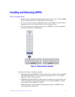
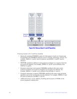
Memory Board A DIMM 8 DIMM 7 DIMM 6 DIMM 5 DIMM 4 DIMM 3 Lock-step pair DIMM 2 DIMM 1 Memory Board B DIMM 8 DIMM 7 DIMM 6 DIMM 5 DIMM 4 DIMM 3 DIMM 2 DIMM 1 Channel 0 Channel 1 Branch 0 Channel 2 Channel 3 Branch 1 Figure 42. Memory Board A and B Population If memory boards A, B, C and D are installed: • Identically numbered FBDIMM sockets for both memory boards in a branch must be populated with FBDIMMs identical in terms of timing, technology, and size. For example, DIMM A1 and B1 must be identical, and DIMM C1 and D1 must be identical. • FBDIMMs installed in different socket positions (numbers) on a memory board do not need to be identical. For example, DIMMs A1 and B1 can be different from DIMMs A2 and B2. • If memory mirroring is not required, FBDIMMs installed in the same socket positions (numbers) across the two branches do not need to be identical. For example, DIMMs A1 and B1 can be different from DIMMs C1 and D1. • If memory mirroring is required, FBDIMMs installed in the same socket positions (numbers) across the two branches must be identical. For example, DIMMs A1 and B1 must be identical to DIMMs C1 and D1. • Additional memory can be added by installing identical pairs of DIMMs in the lowest numbered available slots. 80 Intel® Server System S7000FC4UR Product Guide
-
 1
1 -
2
-
3
-
4
-
5
-
6
-
7
-
8
-
9
-
10
-
11
-
12
-
13
-
14
-
15
-
16
-
17
-
18
-
19
-
20
-
21
-
22
-
23
-
24
-
25
-
26
-
27
-
28
-
29
-
30
-
31
-
32
-
33
-
34
-
35
-
36
-
37
-
38
-
39
-
40
-
41
-
42
-
43
-
44
-
45
-
46
-
47
-
48
-
49
-
50
-
51
-
52
-
53
-
54
-
55
-
56
-
57
-
58
-
59
-
60
-
61
-
62
-
63
-
64
-
65
-
66
-
67
-
68
-
69
-
70
-
71
-
72
-
73
-
74
-
75
-
76
-
77
-
78
-
79
-
80
-
81
-
82
-
83
-
84
-
85
-
86
-
87
-
88
-
89
-
90
-
91
-
92
-
 93
93 -
 94
94 -
 95
95 -
 96
96 -
 97
97 -
 98
98 -
 99
99 -
 100
100 -
 101
101 -
 102
102 -
 103
103 -
104
-
105
-
106
-
107
-
108
-
109
-
110
-
111
-
112
-
113
-
114
-
115
-
116
-
117
-
118
-
119
-
120
-
121
-
122
-
123
-
124
-
125
-
126
-
127
-
128
-
129
-
130
-
131
-
132
-
133
-
134
-
135
-
136
-
137
-
138
-
139
-
140
-
141
-
142
-
143
-
144
-
145
-
146
-
147
-
148
-
149
-
150
-
151
-
152
-
153
-
154
-
155
-
156
-
157
-
158
-
159
-
160
-
161
-
162
-
163
-
164
-
165
-
166
-
167
-
168
-
169
-
170
-
171
-
172
-
173
-
174
-
175
-
176
-
177
-
178
-
179
-
180
-
181
-
182
-
183
-
184
-
185
-
186
-
187
-
188
-
189
-
190
-
191
-
192
-
193
-
194
-
195
-
196
-
197
-
198
-
199
-
200
-
201
-
202
-
203
-
204
-
205
-
206
-
207
-
208
-
209
-
210
-
211
-
212
-
213
-
214
-
215
-
216
-
217
-
218
-
219
-
220
-
221
-
222
-
223
-
224
-
225
-
226
-
227
-
228
-
229
-
230
-
231
-
232
 |
 |
