Intel S7000FC4UR Product Guide - Page 99
Installing DIMMs, Memory Board A, B, C, D Population
 |
UPC - 735858194259
View all Intel S7000FC4UR manuals
Add to My Manuals
Save this manual to your list of manuals |
Page 99 highlights
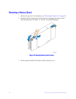
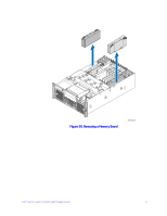
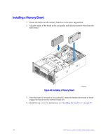
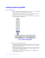
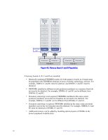
Lock-step pair Branch 0 Memory Board A DIMM 8 DIMM 7 DIMM 6 DIMM 5 DIMM 4 DIMM 3 DIMM 2 DIMM 1 Memory Board B DIMM 8 DIMM 7 DIMM 6 DIMM 5 DIMM 4 DIMM 3 DIMM 2 DIMM 1 Memory Board C DIMM 8 DIMM 7 DIMM 6 DIMM 5 DIMM 4 DIMM 3 DIMM 2 DIMM 1 Memory Board D DIMM 8 DIMM 7 DIMM 6 DIMM 5 DIMM 4 DIMM 3 DIMM 2 DIMM 1 Lock-step pair Branch 1 Channel 0 Channel 1 Branch 0 Channel 2 Channel 3 Branch 1 Figure 43. Memory Board A, B, C, D Population Installing DIMMs Cautions: • Use extreme care when installing a DIMM. Applying too much pressure can damage the connector. DIMMs are keyed and can be inserted in only one way. • Hold DIMMs only by the edges. Do not touch the components or gold edge connectors. • Install DIMMs with gold-plated edge connectors only. • The maximum DIMM height is 4.445 cm (1.75 inches). Do not install DIMMs that exceed this height. 1. Remove the top cover. For instructions, see "Removing the Top Cover" on page 58. 2. Remove the memory board. For instructions, see "Removing a Memory Board" on page 76. 3. Press down on the hooks on the underside of the memory board to disengage them. See letter "A" in the following figure. 4. Lift the memory board DIMM cover from the memory board. Intel® Server System S7000FC4UR Product Guide 81
-
 1
1 -
2
-
3
-
4
-
5
-
6
-
7
-
8
-
9
-
10
-
11
-
12
-
13
-
14
-
15
-
16
-
17
-
18
-
19
-
20
-
21
-
22
-
23
-
24
-
25
-
26
-
27
-
28
-
29
-
30
-
31
-
32
-
33
-
34
-
35
-
36
-
37
-
38
-
39
-
40
-
41
-
42
-
43
-
44
-
45
-
46
-
47
-
48
-
49
-
50
-
51
-
52
-
53
-
54
-
55
-
56
-
57
-
58
-
59
-
60
-
61
-
62
-
63
-
64
-
65
-
66
-
67
-
68
-
69
-
70
-
71
-
72
-
73
-
74
-
75
-
76
-
77
-
78
-
79
-
80
-
81
-
82
-
83
-
84
-
85
-
86
-
87
-
88
-
89
-
90
-
91
-
92
-
93
-
 94
94 -
 95
95 -
 96
96 -
 97
97 -
 98
98 -
 99
99 -
 100
100 -
 101
101 -
 102
102 -
 103
103 -
 104
104 -
105
-
106
-
107
-
108
-
109
-
110
-
111
-
112
-
113
-
114
-
115
-
116
-
117
-
118
-
119
-
120
-
121
-
122
-
123
-
124
-
125
-
126
-
127
-
128
-
129
-
130
-
131
-
132
-
133
-
134
-
135
-
136
-
137
-
138
-
139
-
140
-
141
-
142
-
143
-
144
-
145
-
146
-
147
-
148
-
149
-
150
-
151
-
152
-
153
-
154
-
155
-
156
-
157
-
158
-
159
-
160
-
161
-
162
-
163
-
164
-
165
-
166
-
167
-
168
-
169
-
170
-
171
-
172
-
173
-
174
-
175
-
176
-
177
-
178
-
179
-
180
-
181
-
182
-
183
-
184
-
185
-
186
-
187
-
188
-
189
-
190
-
191
-
192
-
193
-
194
-
195
-
196
-
197
-
198
-
199
-
200
-
201
-
202
-
203
-
204
-
205
-
206
-
207
-
208
-
209
-
210
-
211
-
212
-
213
-
214
-
215
-
216
-
217
-
218
-
219
-
220
-
221
-
222
-
223
-
224
-
225
-
226
-
227
-
228
-
229
-
230
-
231
-
232
 |
 |
