Intel S7000FC4UR Product Guide - Page 90
Installing a Hot-swap PCI Card
 |
UPC - 735858194259
View all Intel S7000FC4UR manuals
Add to My Manuals
Save this manual to your list of manuals |
Page 90 highlights
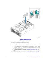
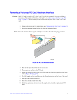
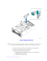
- To install an expansion slot cover: align the cover with the slot from the rear of the chassis. Press the cover into the slot. Rotate the retention latch at the rear of the board slot into the down position. See letter "C" in Figure 35 on page 70. - To install a replacement PCI card: see "Installing a Hot-swap PCI Card" on page 72. 10. Install the top cover. For instructions see "Installing the Top Cover" on page 59. Installing a Hot-swap PCI Card Caution: Only PCI add-in cards in PCI slots 1 and 2 are hot-swappable. If you are installing a PCI card into PCI slots 3 through 7, see "Installing a Non-hot-swap PCI Card" on page 75. When looking at the system from the front, slots 1 and 2 are at the right. 1. If your server is operating, use your operating system or GUI application to power down the PCI slot. 2. Remove the top cover. For instructions, see "Removing the Top Cover" on page 58. 3. Being careful not to touch the components or gold edge-connectors on the add-in card, remove the card from the anti-static bag and place it on a clean, ESDprotected work surface. 4. Record the serial number of the board and any jumpers or switch settings according to the board manufacturer's instructions. Record these settings in your equipment log. 5. Rotate the retention latch at the rear of the card slot into the up position. See letter "A" in the following figure. 6. If an expansion slot cover is installed, remove it by sliding it up. See letter "B" in the figure. 7. Align and slide the adapter board down until it seats in its connector. If you are installing a full-length card, guide the front of the card into the slot shown by letter "D" in the figure. 8. Press the card down firmly until it seats into the slot. 72 Intel® Server System S7000FC4UR Product Guide
-
 1
1 -
2
-
3
-
4
-
5
-
6
-
7
-
8
-
9
-
10
-
11
-
12
-
13
-
14
-
15
-
16
-
17
-
18
-
19
-
20
-
21
-
22
-
23
-
24
-
25
-
26
-
27
-
28
-
29
-
30
-
31
-
32
-
33
-
34
-
35
-
36
-
37
-
38
-
39
-
40
-
41
-
42
-
43
-
44
-
45
-
46
-
47
-
48
-
49
-
50
-
51
-
52
-
53
-
54
-
55
-
56
-
57
-
58
-
59
-
60
-
61
-
62
-
63
-
64
-
65
-
66
-
67
-
68
-
69
-
70
-
71
-
72
-
73
-
74
-
75
-
76
-
77
-
78
-
79
-
80
-
81
-
82
-
83
-
84
-
 85
85 -
 86
86 -
 87
87 -
 88
88 -
 89
89 -
 90
90 -
 91
91 -
 92
92 -
 93
93 -
 94
94 -
 95
95 -
96
-
97
-
98
-
99
-
100
-
101
-
102
-
103
-
104
-
105
-
106
-
107
-
108
-
109
-
110
-
111
-
112
-
113
-
114
-
115
-
116
-
117
-
118
-
119
-
120
-
121
-
122
-
123
-
124
-
125
-
126
-
127
-
128
-
129
-
130
-
131
-
132
-
133
-
134
-
135
-
136
-
137
-
138
-
139
-
140
-
141
-
142
-
143
-
144
-
145
-
146
-
147
-
148
-
149
-
150
-
151
-
152
-
153
-
154
-
155
-
156
-
157
-
158
-
159
-
160
-
161
-
162
-
163
-
164
-
165
-
166
-
167
-
168
-
169
-
170
-
171
-
172
-
173
-
174
-
175
-
176
-
177
-
178
-
179
-
180
-
181
-
182
-
183
-
184
-
185
-
186
-
187
-
188
-
189
-
190
-
191
-
192
-
193
-
194
-
195
-
196
-
197
-
198
-
199
-
200
-
201
-
202
-
203
-
204
-
205
-
206
-
207
-
208
-
209
-
210
-
211
-
212
-
213
-
214
-
215
-
216
-
217
-
218
-
219
-
220
-
221
-
222
-
223
-
224
-
225
-
226
-
227
-
228
-
229
-
230
-
231
-
232
 |
 |
