Intel S7000FC4UR Product Guide - Page 23
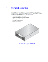
Front Control Panel, Local Control Panel
 |
UPC - 735858194259
View all Intel S7000FC4UR manuals
Add to My Manuals
Save this manual to your list of manuals |
Page 23 highlights
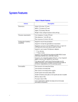
Front Control Panel You can choose between the standard control panel or the Intel® Local Control Panel to monitor and control your system locally. The standard control panel provides the following user interface for system management and status LEDs. Item Feature Description Front Panel Connectors A Video connector Standard VGA-compatible video port B Three USB connectors 2.0 port, 4-pin connectors Front Panel Buttons and LED Indicators C Hard drive activity Green / amber LED that indicates hard drive activity and faults LED LED State Drive State Green on SAS drives are installed and functioning correctly NOTE: LED may blink if all drives are active at the same time. Green blink SATA drives are installed and active Amber on Drive / slot failure Amber slow blink Predictive hard drive / slot failure or rebuild in process (~1 Hz) Amber fast blink Rebuild interrupted or rebuild on empty slot (~2.5 Hz) Intel® Server System S7000FC4UR Product Guide 5
-
 1
1 -
2
-
3
-
4
-
5
-
6
-
7
-
8
-
9
-
10
-
11
-
12
-
13
-
14
-
15
-
16
-
17
-
 18
18 -
 19
19 -
 20
20 -
 21
21 -
 22
22 -
 23
23 -
 24
24 -
 25
25 -
 26
26 -
 27
27 -
 28
28 -
29
-
30
-
31
-
32
-
33
-
34
-
35
-
36
-
37
-
38
-
39
-
40
-
41
-
42
-
43
-
44
-
45
-
46
-
47
-
48
-
49
-
50
-
51
-
52
-
53
-
54
-
55
-
56
-
57
-
58
-
59
-
60
-
61
-
62
-
63
-
64
-
65
-
66
-
67
-
68
-
69
-
70
-
71
-
72
-
73
-
74
-
75
-
76
-
77
-
78
-
79
-
80
-
81
-
82
-
83
-
84
-
85
-
86
-
87
-
88
-
89
-
90
-
91
-
92
-
93
-
94
-
95
-
96
-
97
-
98
-
99
-
100
-
101
-
102
-
103
-
104
-
105
-
106
-
107
-
108
-
109
-
110
-
111
-
112
-
113
-
114
-
115
-
116
-
117
-
118
-
119
-
120
-
121
-
122
-
123
-
124
-
125
-
126
-
127
-
128
-
129
-
130
-
131
-
132
-
133
-
134
-
135
-
136
-
137
-
138
-
139
-
140
-
141
-
142
-
143
-
144
-
145
-
146
-
147
-
148
-
149
-
150
-
151
-
152
-
153
-
154
-
155
-
156
-
157
-
158
-
159
-
160
-
161
-
162
-
163
-
164
-
165
-
166
-
167
-
168
-
169
-
170
-
171
-
172
-
173
-
174
-
175
-
176
-
177
-
178
-
179
-
180
-
181
-
182
-
183
-
184
-
185
-
186
-
187
-
188
-
189
-
190
-
191
-
192
-
193
-
194
-
195
-
196
-
197
-
198
-
199
-
200
-
201
-
202
-
203
-
204
-
205
-
206
-
207
-
208
-
209
-
210
-
211
-
212
-
213
-
214
-
215
-
216
-
217
-
218
-
219
-
220
-
221
-
222
-
223
-
224
-
225
-
226
-
227
-
228
-
229
-
230
-
231
-
232
 |
 |
