3Com 3C63311 Reference Guide - Page 103
Activation/Deactivation Bit Error Rates, Activation Min.
 |
View all 3Com 3C63311 manuals
Add to My Manuals
Save this manual to your list of manuals |
Page 103 highlights
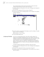
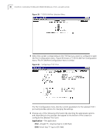
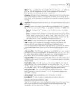
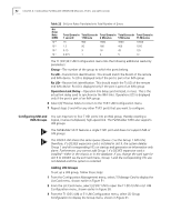
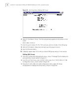
Configuring the T1/E1 Interface 91 LBO (T1 only)-Line Build Out. The setting for the transmit signal level: 0, 7.5, 15, or 22 db. The LBO compensates for the distance between the card and the CSU/repeater. It is a setting for the transmit signal level. Framing-The type of frame organization configured for the T1/E1 port interface: D4 or ESF for T1. For E1 Framing is a read-only parameters and is always set to multi-frame. Set this parameter to match the service provider or device connection framing. CAUTION: A framing mismatch can cause LOF, OOF alarm conditions and result in traffic loss. Timing (T1 only)-The type of input clock service configured for the T1 module. Set the timing source to system if you are using the T1 module as a trunk module. System-Configures the T1 module to use the internal clock as the timing source. Loop-Configures the T1 module to use the input port Rx clock as the timing source; timing is received from the service "loop." Select Loop if the T1 UNI module is used for the network/carrier service termination, in which case the carrier (the service "loop") typically provides the timing source. Gain Limit (T1 only)-The setting for the receive signal level: 26 or 36 dB. AFA-Enables (yes) or disables (no) Automatic Frequency Adjustment. AFA monitors the error rate detected by the CRC (cyclic redundancy check) error-checking scheme of each of the T1/E1 links (ports). It automatically disables and re-enables a port when the error rate on that port is at a set level for a set time. Activation Rate-The CRC (cyclic redundancy check) BER (bit error rate) at which AFA takes a link out of service based on the Activation Min.: 10-4, 10-5, 10-6, 10-7. For further details about setting this parameter, see "Activation/Deactivation Bit Error Rates" below. This parameter appears only when AFA is enabled. Activation Min.-The period during which AFA monitors the link condition prior to taking it out of service, in minutes: 1 to 15. This parameter appears only when AFA is enabled. Deactivation Rate-The CRC (cyclic redundancy check) BER (bit error rate) at which AFA puts a link in service based on the Deactivation Min.: 10-4, 10-5, 10-6, 10-7. For further details about setting this parameter, see "Activation/Deactivation Bit Error Rates" below. This parameter appears only when AFA is enabled. Deactivation Min.-The period during which AFA monitors the link condition prior to putting it in service, in minutes: 1 to 15. This parameter appears only when AFA is enabled. Admin Status-Administrative status: Out of Service or In Service. Inband Lpbk (T1 only)-Enables or disables inband loopback detection. Activation/Deactivation Bit Error Rates Table 22 translates bit errors rates into the total number of errors for various time periods. Use this table as a reference when you are selecting activation and deactivation bit error rates for the AFA feature.
-
 1
1 -
2
-
3
-
4
-
5
-
6
-
7
-
8
-
9
-
10
-
11
-
12
-
13
-
14
-
15
-
16
-
17
-
18
-
19
-
20
-
21
-
22
-
23
-
24
-
25
-
26
-
27
-
28
-
29
-
30
-
31
-
32
-
33
-
34
-
35
-
36
-
37
-
38
-
39
-
40
-
41
-
42
-
43
-
44
-
45
-
46
-
47
-
48
-
49
-
50
-
51
-
52
-
53
-
54
-
55
-
56
-
57
-
58
-
59
-
60
-
61
-
62
-
63
-
64
-
65
-
66
-
67
-
68
-
69
-
70
-
71
-
72
-
73
-
74
-
75
-
76
-
77
-
78
-
79
-
80
-
81
-
82
-
83
-
84
-
85
-
86
-
87
-
88
-
89
-
90
-
91
-
92
-
93
-
94
-
95
-
96
-
97
-
 98
98 -
 99
99 -
 100
100 -
 101
101 -
 102
102 -
 103
103 -
 104
104 -
 105
105 -
 106
106 -
 107
107 -
 108
108 -
109
-
110
-
111
-
112
-
113
-
114
-
115
-
116
-
117
-
118
-
119
-
120
-
121
-
122
-
123
-
124
-
125
-
126
-
127
-
128
-
129
-
130
-
131
-
132
-
133
-
134
-
135
-
136
-
137
-
138
-
139
-
140
-
141
-
142
-
143
-
144
-
145
-
146
-
147
-
148
-
149
-
150
-
151
-
152
-
153
-
154
-
155
-
156
-
157
-
158
-
159
-
160
-
161
-
162
-
163
-
164
-
165
-
166
-
167
-
168
-
169
-
170
-
171
-
172
-
173
-
174
-
175
-
176
-
177
-
178
-
179
-
180
-
181
-
182
-
183
-
184
-
185
-
186
-
187
-
188
-
189
-
190
-
191
-
192
-
193
-
194
-
195
-
196
-
197
-
198
-
199
-
200
-
201
-
202
-
203
-
204
-
205
-
206
-
207
-
208
-
209
-
210
-
211
-
212
-
213
-
214
-
215
-
216
-
217
-
218
-
219
-
220
-
221
-
222
-
223
-
224
-
225
-
226
-
227
-
228
-
229
-
230
-
231
-
232
-
233
-
234
-
235
-
236
-
237
-
238
-
239
-
240
-
241
-
242
-
243
-
244
-
245
-
246
-
247
-
248
-
249
-
250
-
251
-
252
-
253
-
254
-
255
-
256
-
257
-
258
-
259
-
260
-
261
-
262
 |
 |