3Com 3C63311 Reference Guide - Page 151
Configuring CBR Circuits for DBA, Checking the Data Bytes to Determine a DBA Bits Mask Setting
 |
View all 3Com 3C63311 manuals
Add to My Manuals
Save this manual to your list of manuals |
Page 151 highlights
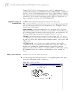
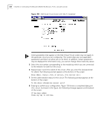
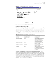
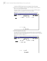
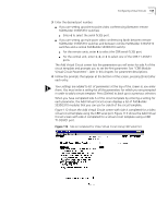
Configuring Virtual Circuits 139 Figure 109 Completed Data Port VCC Virtual Circuit 9 Press any key to return to the Virtual Circuit menu. Configuring CBR Circuits for DBA This section provides guidelines for configuring CBR circuits for various types of dynamic bandwidth allocation (DBA)-both for CAS (channel associated signaling) and CCS (common channel signaling applications). Table 25 summarizes the key CBR port and virtual circuit parameters for these types of applications. For details about how DBA works, see "DS0 Signaling and Dynamic Bandwidth Allocation" in Appendix B. Table 25 CBR Port and Circuit Settings for CAS versus CCS Parameter Port Mode Port Data Bits Mask Setting for CAS Structured Voice N/A VC Payload Size/Type VC Onhook Detection VC Mode Voice Enabled N/A Setting for CCS Structured Data Leave at default setting (127) in most cases; for details see "Checking the Data Bytes to Determine a DBA Bits Mask Setting" after this table Set automatically when VC Mode set to DBA Set automatically when VC Mode set to DBA DBA for channels 1-23 (DSX-1) or 1-15 and 17-31 (E1) Normal for channel 24 (DSX-1) or 16 (E1) Checking the Data Bytes to Determine a DBA Bits Mask Setting CCS monitors for voice activity. In most cases the default DBA Bits Mask (127) works, but if you are having a problem with a CCS circuit, you can set the DBA Bits Mask to monitor any bits. The unit will monitor the virtual circuit, and you can use the activity reported on the channel (reported under CBR ATM statistics as Data Bytes To) to determine the proper DBA Bits Mask. For details about checking the data bytes, see "CBR ATM Statistics" in Chapter 5.
-
 1
1 -
2
-
3
-
4
-
5
-
6
-
7
-
8
-
9
-
10
-
11
-
12
-
13
-
14
-
15
-
16
-
17
-
18
-
19
-
20
-
21
-
22
-
23
-
24
-
25
-
26
-
27
-
28
-
29
-
30
-
31
-
32
-
33
-
34
-
35
-
36
-
37
-
38
-
39
-
40
-
41
-
42
-
43
-
44
-
45
-
46
-
47
-
48
-
49
-
50
-
51
-
52
-
53
-
54
-
55
-
56
-
57
-
58
-
59
-
60
-
61
-
62
-
63
-
64
-
65
-
66
-
67
-
68
-
69
-
70
-
71
-
72
-
73
-
74
-
75
-
76
-
77
-
78
-
79
-
80
-
81
-
82
-
83
-
84
-
85
-
86
-
87
-
88
-
89
-
90
-
91
-
92
-
93
-
94
-
95
-
96
-
97
-
98
-
99
-
100
-
101
-
102
-
103
-
104
-
105
-
106
-
107
-
108
-
109
-
110
-
111
-
112
-
113
-
114
-
115
-
116
-
117
-
118
-
119
-
120
-
121
-
122
-
123
-
124
-
125
-
126
-
127
-
128
-
129
-
130
-
131
-
132
-
133
-
134
-
135
-
136
-
137
-
138
-
139
-
140
-
141
-
142
-
143
-
144
-
145
-
 146
146 -
 147
147 -
 148
148 -
 149
149 -
 150
150 -
 151
151 -
 152
152 -
 153
153 -
 154
154 -
 155
155 -
 156
156 -
157
-
158
-
159
-
160
-
161
-
162
-
163
-
164
-
165
-
166
-
167
-
168
-
169
-
170
-
171
-
172
-
173
-
174
-
175
-
176
-
177
-
178
-
179
-
180
-
181
-
182
-
183
-
184
-
185
-
186
-
187
-
188
-
189
-
190
-
191
-
192
-
193
-
194
-
195
-
196
-
197
-
198
-
199
-
200
-
201
-
202
-
203
-
204
-
205
-
206
-
207
-
208
-
209
-
210
-
211
-
212
-
213
-
214
-
215
-
216
-
217
-
218
-
219
-
220
-
221
-
222
-
223
-
224
-
225
-
226
-
227
-
228
-
229
-
230
-
231
-
232
-
233
-
234
-
235
-
236
-
237
-
238
-
239
-
240
-
241
-
242
-
243
-
244
-
245
-
246
-
247
-
248
-
249
-
250
-
251
-
252
-
253
-
254
-
255
-
256
-
257
-
258
-
259
-
260
-
261
-
262
 |
 |
