3Com 3C63311 Reference Guide - Page 164
Frame Relay Virtual Circuit Parameters, Interworking Mode, Start/End Frame Relay DLCI
 |
View all 3Com 3C63311 manuals
Add to My Manuals
Save this manual to your list of manuals |
Page 164 highlights
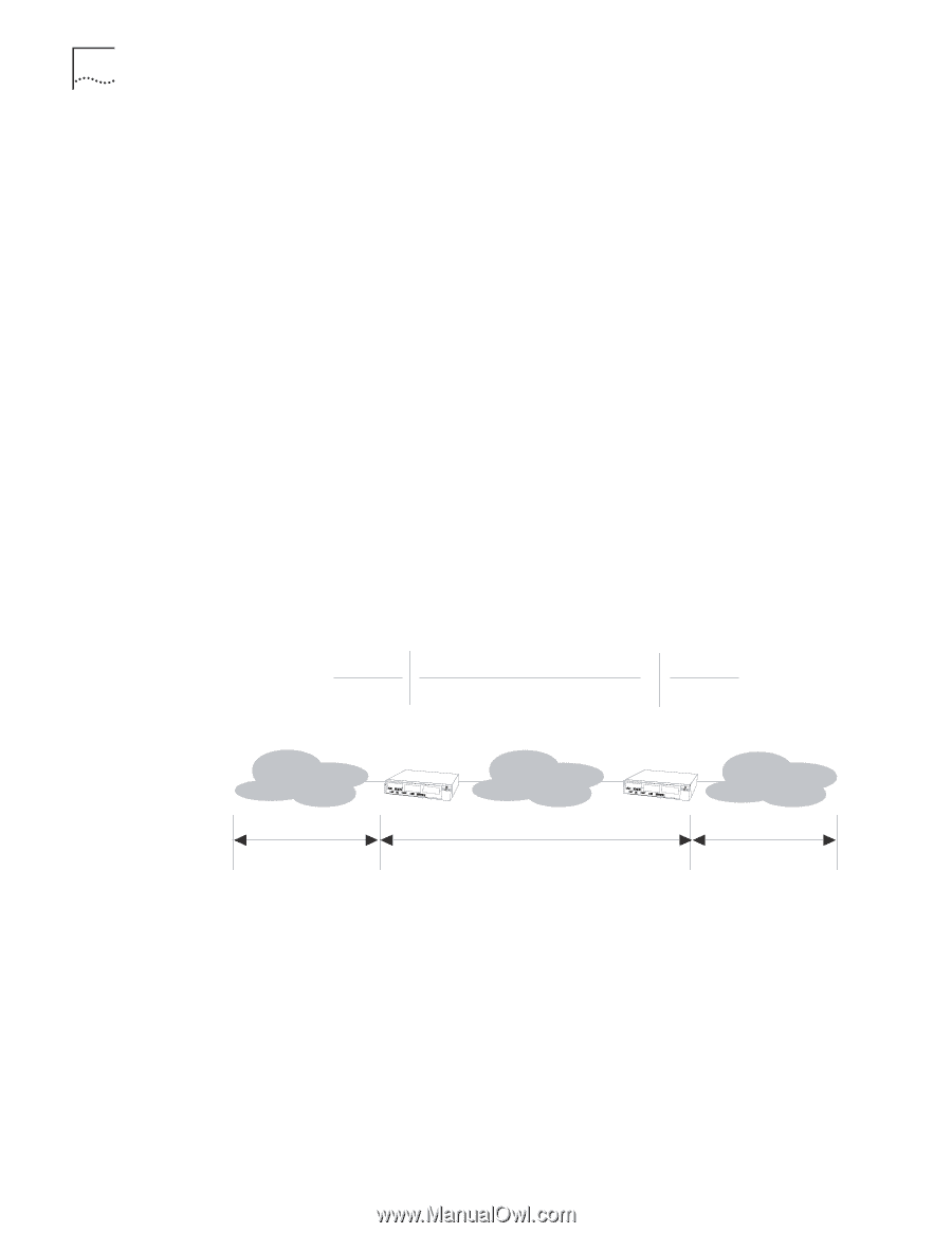
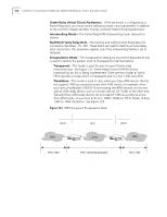
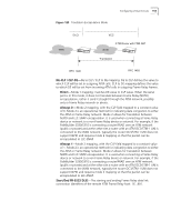
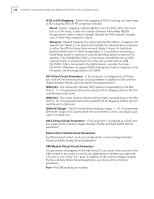
152 CHAPTER 4: CONFIGURING PATHBUILDER S330/S310 MODULES, PORTS, AND APPLICATIONS Frame Relay Virtual Circuit Parameters If the serial port is configured as a Frame Relay port, you must set the following virtual circuit parameters in addition to the common Shaper Number, Priority, and Early Packet Discard parameters: Interworking Mode-The Frame Relay/ATM interworking mode: Network or Service. Start/End Frame Relay DLCI-The starting and ending Frame Relay data link connection identifiers: 16...991. These DLCIs are used to identify a Frame Relay local connection. This parameter applies only if the Interworking Mode is set to Network. Encapsulation Mode-The encapsulation data goes around the data packet and is used to identify the packet; enter 1 (Transparent) or 2 (Translation). Transparent-This mode is used for point-to-point frame relay interconnection. See Figure 123. Frame Relay Forum 8 (FRF.8) Service Interworking for this is being implemented. There are two modes at which FRF.8 specifies a mode which is transparent and is in fact 1490 over ATM. Translation-This mode is used in cases when you have ATM devices that do not support 1490 as a protocol across their ATM trunks; for example, when you have a PathBuilder S330/S310 terminating the ATM network at one end and an ATM-ready device, such as a router with an OC-3 UNI, at the other end. Typically these ATM-ready devices do not support 1490 as a protocol across their ATM trunks, so you have to do LLC_SNAP (1483) per FRF.8. Mode 1F does 1490 to 1483 translation. See Figure 124. Figure 123 FRF.8 Transparent Encapsulation Mode DLCI FRR VCC A TM DLCI FRR RFC 1490 RFC 1433 Encapsulated RFC 1490
-
 1
1 -
2
-
3
-
4
-
5
-
6
-
7
-
8
-
9
-
10
-
11
-
12
-
13
-
14
-
15
-
16
-
17
-
18
-
19
-
20
-
21
-
22
-
23
-
24
-
25
-
26
-
27
-
28
-
29
-
30
-
31
-
32
-
33
-
34
-
35
-
36
-
37
-
38
-
39
-
40
-
41
-
42
-
43
-
44
-
45
-
46
-
47
-
48
-
49
-
50
-
51
-
52
-
53
-
54
-
55
-
56
-
57
-
58
-
59
-
60
-
61
-
62
-
63
-
64
-
65
-
66
-
67
-
68
-
69
-
70
-
71
-
72
-
73
-
74
-
75
-
76
-
77
-
78
-
79
-
80
-
81
-
82
-
83
-
84
-
85
-
86
-
87
-
88
-
89
-
90
-
91
-
92
-
93
-
94
-
95
-
96
-
97
-
98
-
99
-
100
-
101
-
102
-
103
-
104
-
105
-
106
-
107
-
108
-
109
-
110
-
111
-
112
-
113
-
114
-
115
-
116
-
117
-
118
-
119
-
120
-
121
-
122
-
123
-
124
-
125
-
126
-
127
-
128
-
129
-
130
-
131
-
132
-
133
-
134
-
135
-
136
-
137
-
138
-
139
-
140
-
141
-
142
-
143
-
144
-
145
-
146
-
147
-
148
-
149
-
150
-
151
-
152
-
153
-
154
-
155
-
156
-
157
-
158
-
 159
159 -
 160
160 -
 161
161 -
 162
162 -
 163
163 -
 164
164 -
 165
165 -
 166
166 -
 167
167 -
 168
168 -
 169
169 -
170
-
171
-
172
-
173
-
174
-
175
-
176
-
177
-
178
-
179
-
180
-
181
-
182
-
183
-
184
-
185
-
186
-
187
-
188
-
189
-
190
-
191
-
192
-
193
-
194
-
195
-
196
-
197
-
198
-
199
-
200
-
201
-
202
-
203
-
204
-
205
-
206
-
207
-
208
-
209
-
210
-
211
-
212
-
213
-
214
-
215
-
216
-
217
-
218
-
219
-
220
-
221
-
222
-
223
-
224
-
225
-
226
-
227
-
228
-
229
-
230
-
231
-
232
-
233
-
234
-
235
-
236
-
237
-
238
-
239
-
240
-
241
-
242
-
243
-
244
-
245
-
246
-
247
-
248
-
249
-
250
-
251
-
252
-
253
-
254
-
255
-
256
-
257
-
258
-
259
-
260
-
261
-
262
 |
 |