3Com 3C63311 Reference Guide - Page 49
Step 2: Install the Unit in the Rack, CAUTION
 |
View all 3Com 3C63311 manuals
Add to My Manuals
Save this manual to your list of manuals |
Page 49 highlights
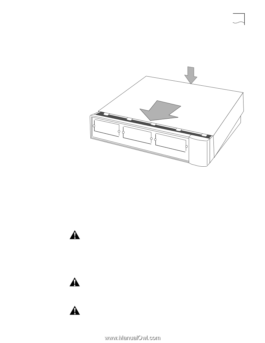
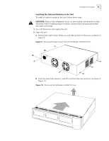
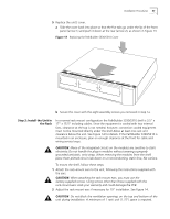
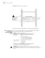
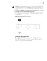
Installation Procedures 37 5 Replace the unit's cover. a Slide the cover back into place so that the five tabs go under the lip of the front panel (arrow 1) and push it down at the rear (arrow 2), as shown in Figure 13. Figure 13 Replacing the PathBuilder S330/S310 Cover 2 1 b Secure the cover with the eight assembly screws you removed in step 1a. Step 2: Install the Unit in the Rack In a normal rack mount configuration the PathBuilder S330/S310 shelf is 3.5" x 17" x 15.5" including cables. Since the equipment is cooled with two internal fans, clearance at the top is not needed; however, convection cooled equipment must not be mounted directly under the shelf.Allow at least one rack unit clearance below the unit. See Figure 14 for details. If the PathBuilder S330/S310 is mounted in an enclosure, plan on enough clearance at the front for cable and wiring service loops. CAUTION: Many of the integrated circuits on the modules are sensitive to static electricity. Do not handle the plug-in modules without wearing a properly grounded antistatic, wrist strap. When removing the modules from the shelf, place them printed-circuit side down on a nonconducting, static-free, flat surface. To mount the shelf, follow these steps: 1 Attach the rack-mount ears to the unit, following the instructions supplied with the ears. CAUTION: When attaching the rack-mount ears, you must use the factory-supplied screws. Using screws other than those supplied with the rack-mount ears voids your warranty and could damage the PCB. 2 Adjust the rack-mount ears if necessary for 19" installation. See Figure 14. CAUTION: Do not block the ventilation openings on the top and bottom of the unit during installation. A minimum of 1 rack unit (1.75") space is required.
-
 1
1 -
2
-
3
-
4
-
5
-
6
-
7
-
8
-
9
-
10
-
11
-
12
-
13
-
14
-
15
-
16
-
17
-
18
-
19
-
20
-
21
-
22
-
23
-
24
-
25
-
26
-
27
-
28
-
29
-
30
-
31
-
32
-
33
-
34
-
35
-
36
-
37
-
38
-
39
-
40
-
41
-
42
-
43
-
 44
44 -
 45
45 -
 46
46 -
 47
47 -
 48
48 -
 49
49 -
 50
50 -
 51
51 -
 52
52 -
 53
53 -
 54
54 -
55
-
56
-
57
-
58
-
59
-
60
-
61
-
62
-
63
-
64
-
65
-
66
-
67
-
68
-
69
-
70
-
71
-
72
-
73
-
74
-
75
-
76
-
77
-
78
-
79
-
80
-
81
-
82
-
83
-
84
-
85
-
86
-
87
-
88
-
89
-
90
-
91
-
92
-
93
-
94
-
95
-
96
-
97
-
98
-
99
-
100
-
101
-
102
-
103
-
104
-
105
-
106
-
107
-
108
-
109
-
110
-
111
-
112
-
113
-
114
-
115
-
116
-
117
-
118
-
119
-
120
-
121
-
122
-
123
-
124
-
125
-
126
-
127
-
128
-
129
-
130
-
131
-
132
-
133
-
134
-
135
-
136
-
137
-
138
-
139
-
140
-
141
-
142
-
143
-
144
-
145
-
146
-
147
-
148
-
149
-
150
-
151
-
152
-
153
-
154
-
155
-
156
-
157
-
158
-
159
-
160
-
161
-
162
-
163
-
164
-
165
-
166
-
167
-
168
-
169
-
170
-
171
-
172
-
173
-
174
-
175
-
176
-
177
-
178
-
179
-
180
-
181
-
182
-
183
-
184
-
185
-
186
-
187
-
188
-
189
-
190
-
191
-
192
-
193
-
194
-
195
-
196
-
197
-
198
-
199
-
200
-
201
-
202
-
203
-
204
-
205
-
206
-
207
-
208
-
209
-
210
-
211
-
212
-
213
-
214
-
215
-
216
-
217
-
218
-
219
-
220
-
221
-
222
-
223
-
224
-
225
-
226
-
227
-
228
-
229
-
230
-
231
-
232
-
233
-
234
-
235
-
236
-
237
-
238
-
239
-
240
-
241
-
242
-
243
-
244
-
245
-
246
-
247
-
248
-
249
-
250
-
251
-
252
-
253
-
254
-
255
-
256
-
257
-
258
-
259
-
260
-
261
-
262
 |
 |