3Com 3C63311 Reference Guide - Page 104
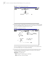
Configuring UNI and IMA Groups, From the T1 DS1 UNI or E1 UNI Configuration menu, select
 |
View all 3Com 3C63311 manuals
Add to My Manuals
Save this manual to your list of manuals |
Page 104 highlights
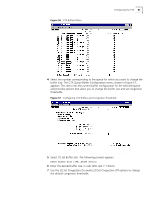
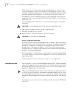
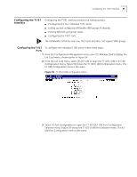
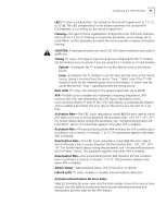
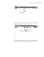
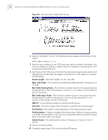
92 CHAPTER 4: CONFIGURING PATHBUILDER S330/S310 MODULES, PORTS, AND APPLICATIONS Table 22 Bit Error Rates Translated into Total Number of Errors Bit Error Rate (BER) 10-4 10-5 10-6 10-7 Total Errors in Total Errors in Total Errors in Total Errors in Total Errors in 1 second 1 Minute 2 Minutes 5 Minutes 15 Minutes 15 900 1800 4500 13500 1.5 90 180 450 1350 0.15 9 18 45 135 0.015 1 2 5 13 The T1 (DS1)/E1 UNI Configuration menu lists the following additional read-only parameters: Group-The number of the group to which the ports belong. Tx LID-Transmit link identification. This should match the Rx LID of the remote end IMA device. Tx LID is displayed only if the port is part of an IMA group. Rx LID-Receive link identification. This should match the Tx LID of the remote end IMA device. Rx LID is displayed only if the port is part of an IMA group. Operation Link Delay-Operation link delay synchronized, in msec. This is the actual link delay used to synchronize the IMA links. Operations LDS is displayed only if the port is part of an IMA group. 6 Select [9] Previous Menu to return to the T1/E1 UNI Configuration menu. 7 Repeat steps 3 and 4 for any other T1/E1 ports that you want to configure. Configuring UNI and You can map two to four T1/E1 ports into an IMA group, thereby creating a IMA Groups logical, inverse-multiplexed, high-speed link. The PathBuilder S330 also supports UNI groups. The PathBuilder S310 features a single T1/E1 port and does not support IMA or UNI groups. The DS3/E3 UNI shares the same queue (Queue 1) as the Group 1 IMA UNI; therefore, if a DS3/E3 expansion card is installed in slot 9, the system deletes Group 1 and all corresponding VCs on startup and generates an information only alarm. Furthermore, you cannot add Group 1 if a DS3/E3 expansion card is installed-either in the chassis or in the database. If you change the card type for slot 9 to DS3/E3 via the List Card menu, Group 1 and the corresponding VCs are not deleted until the system is restarted. Adding UNI Groups To set up a UNI group, follow these steps: 1 From the Configuration Management menu, select [1] Manage Card to display the List Card menu, shown earlier in Figure 51. 2 From the List Card menu, select [3] DS1 UNI to open the T1 (DS1) UNI or E1 UNI Configuration menu, shown earlier in Figure 58. 3 From the T1 (DS1) UNI or E1 UNI Configuration menu, select [3] Group Configuration to display the Group menu, shown in Figure 61.
-
 1
1 -
2
-
3
-
4
-
5
-
6
-
7
-
8
-
9
-
10
-
11
-
12
-
13
-
14
-
15
-
16
-
17
-
18
-
19
-
20
-
21
-
22
-
23
-
24
-
25
-
26
-
27
-
28
-
29
-
30
-
31
-
32
-
33
-
34
-
35
-
36
-
37
-
38
-
39
-
40
-
41
-
42
-
43
-
44
-
45
-
46
-
47
-
48
-
49
-
50
-
51
-
52
-
53
-
54
-
55
-
56
-
57
-
58
-
59
-
60
-
61
-
62
-
63
-
64
-
65
-
66
-
67
-
68
-
69
-
70
-
71
-
72
-
73
-
74
-
75
-
76
-
77
-
78
-
79
-
80
-
81
-
82
-
83
-
84
-
85
-
86
-
87
-
88
-
89
-
90
-
91
-
92
-
93
-
94
-
95
-
96
-
97
-
98
-
 99
99 -
 100
100 -
 101
101 -
 102
102 -
 103
103 -
 104
104 -
 105
105 -
 106
106 -
 107
107 -
 108
108 -
 109
109 -
110
-
111
-
112
-
113
-
114
-
115
-
116
-
117
-
118
-
119
-
120
-
121
-
122
-
123
-
124
-
125
-
126
-
127
-
128
-
129
-
130
-
131
-
132
-
133
-
134
-
135
-
136
-
137
-
138
-
139
-
140
-
141
-
142
-
143
-
144
-
145
-
146
-
147
-
148
-
149
-
150
-
151
-
152
-
153
-
154
-
155
-
156
-
157
-
158
-
159
-
160
-
161
-
162
-
163
-
164
-
165
-
166
-
167
-
168
-
169
-
170
-
171
-
172
-
173
-
174
-
175
-
176
-
177
-
178
-
179
-
180
-
181
-
182
-
183
-
184
-
185
-
186
-
187
-
188
-
189
-
190
-
191
-
192
-
193
-
194
-
195
-
196
-
197
-
198
-
199
-
200
-
201
-
202
-
203
-
204
-
205
-
206
-
207
-
208
-
209
-
210
-
211
-
212
-
213
-
214
-
215
-
216
-
217
-
218
-
219
-
220
-
221
-
222
-
223
-
224
-
225
-
226
-
227
-
228
-
229
-
230
-
231
-
232
-
233
-
234
-
235
-
236
-
237
-
238
-
239
-
240
-
241
-
242
-
243
-
244
-
245
-
246
-
247
-
248
-
249
-
250
-
251
-
252
-
253
-
254
-
255
-
256
-
257
-
258
-
259
-
260
-
261
-
262
 |
 |
