3Com 3C63311 Reference Guide - Page 168
VC and VP Address Translation, Viewing Existing Virtual Circuits
 |
View all 3Com 3C63311 manuals
Add to My Manuals
Save this manual to your list of manuals |
Page 168 highlights
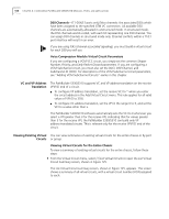
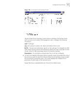
156 CHAPTER 4: CONFIGURING PATHBUILDER S330/S310 MODULES, PORTS, AND APPLICATIONS DS0 Channels-(T1-DSX/E1 ports only) Telco channels: the associated DS0s which have been assigned to the specified ATM VC connection. All available DS0 channels are automatically allocated in unstructured mode. In structured mode, the DS0 channels are bit-coded, with each bit representing one DS0 channel. You can assign DS0 channels in structured mode only. Channel conflicts within a T1/E1 port interface will result in an error. If you are using CAS (channel associated signaling), you must build a virtual circuit for each DS0 you will use. Voice Compression Module Virtual Circuit Parameters If you are configuring a VCM VCC circuit, you simply set the common Shaper Number, Priority, and Early Packet Discard parameters. If you are configuring a VCM Subchannel circuit, you must also set the DLCI, DS0 Channel, and Subchannel ID (SCID). For descriptions of the VCM Subchannel circuit parameters, see "Adding VCM Subchannel Circuits" earlier in this chapter. VC and VP Address Translation The PathBuilder S330/S310 supports VC and VP address translation on the receive VPI/VCI end of a circuit. n To configure VP address translation, set the receive VCI to * when you enter the circuit address in the Add Virtual Circuit menu. This rule applies for all valid values of VPI (0 to 255). n To configure VC address translation, set the VPI in the range 0 to 3, and set the VCI to a value other than x. The PathBuilder S330/S310 software automatically sets the VCI to 0 whenever you select a VPI greater than 3 for the receive VPI, indicating that for values greater than 3 for the receive VPI, the PathBuilder S330/S310 can build only VP address-translated circuits. This is relevant only for the receive VPI/VCI end of the circuit. Viewing Existing Virtual You can view summaries of existing virtual circuits for the entire chassis or by port Circuits or group. Viewing Virtual Circuits for the Entire Chassis To view a summary of existing virtual circuits for the entire chassis, follow these steps: 1 From the Virtual Circuit menu, select [1] List Virtual Circuits to open the List Virtual Circuit Summary screen, shown in Figure 125. The List Virtual Circuit summary screen, shown in Figure 125, appears. This screen shows a summary of all virtual circuits, with a virtual circuit number (VC#) assigned to each.
-
 1
1 -
2
-
3
-
4
-
5
-
6
-
7
-
8
-
9
-
10
-
11
-
12
-
13
-
14
-
15
-
16
-
17
-
18
-
19
-
20
-
21
-
22
-
23
-
24
-
25
-
26
-
27
-
28
-
29
-
30
-
31
-
32
-
33
-
34
-
35
-
36
-
37
-
38
-
39
-
40
-
41
-
42
-
43
-
44
-
45
-
46
-
47
-
48
-
49
-
50
-
51
-
52
-
53
-
54
-
55
-
56
-
57
-
58
-
59
-
60
-
61
-
62
-
63
-
64
-
65
-
66
-
67
-
68
-
69
-
70
-
71
-
72
-
73
-
74
-
75
-
76
-
77
-
78
-
79
-
80
-
81
-
82
-
83
-
84
-
85
-
86
-
87
-
88
-
89
-
90
-
91
-
92
-
93
-
94
-
95
-
96
-
97
-
98
-
99
-
100
-
101
-
102
-
103
-
104
-
105
-
106
-
107
-
108
-
109
-
110
-
111
-
112
-
113
-
114
-
115
-
116
-
117
-
118
-
119
-
120
-
121
-
122
-
123
-
124
-
125
-
126
-
127
-
128
-
129
-
130
-
131
-
132
-
133
-
134
-
135
-
136
-
137
-
138
-
139
-
140
-
141
-
142
-
143
-
144
-
145
-
146
-
147
-
148
-
149
-
150
-
151
-
152
-
153
-
154
-
155
-
156
-
157
-
158
-
159
-
160
-
161
-
162
-
 163
163 -
 164
164 -
 165
165 -
 166
166 -
 167
167 -
 168
168 -
 169
169 -
 170
170 -
 171
171 -
 172
172 -
 173
173 -
174
-
175
-
176
-
177
-
178
-
179
-
180
-
181
-
182
-
183
-
184
-
185
-
186
-
187
-
188
-
189
-
190
-
191
-
192
-
193
-
194
-
195
-
196
-
197
-
198
-
199
-
200
-
201
-
202
-
203
-
204
-
205
-
206
-
207
-
208
-
209
-
210
-
211
-
212
-
213
-
214
-
215
-
216
-
217
-
218
-
219
-
220
-
221
-
222
-
223
-
224
-
225
-
226
-
227
-
228
-
229
-
230
-
231
-
232
-
233
-
234
-
235
-
236
-
237
-
238
-
239
-
240
-
241
-
242
-
243
-
244
-
245
-
246
-
247
-
248
-
249
-
250
-
251
-
252
-
253
-
254
-
255
-
256
-
257
-
258
-
259
-
260
-
261
-
262
 |
 |
