3Com 3C63311 Reference Guide - Page 222
CTX Output Queues and Memory Partition, Open the CTX Buffers menu.
 |
View all 3Com 3C63311 manuals
Add to My Manuals
Save this manual to your list of manuals |
Page 222 highlights
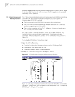
210 APPENDIX B: PATHBUILDER S330/S310 MODULE AND APPLICATION OVERVIEW enabled, an early packet discard operation is performed to check if the cell needs to be discarded. Counters for cells received and cells dropped are also updated, depending on the operation. CTX Output Queues and Memory Partition The CTX is an output buffered switch, with a bus capacity of 400Mbits total. It can store 64K cells. The CTX terminates three Utopia buses, each capable of terminating an OC3/STM-1 payload. n The first bus carries the OC3/STM-1 interface on the motherboard. n The second bus is shared between the SAR and expansion slot 7; both are treated as separate ports in the switch. n The third bus is used by the four T1/E1 UNI ports; this bus can handle up to four separate ports in the switch. The output buffer is statically divided on power up into 256 cell blocks. Any number of blocks can be allocated to any queue. The software sets up a reasonable default configuration, as listed on the CTX Buffers menu, shown in Figure 152. To modify the CTX Buffers, follow these steps: 1 Open the CTX Buffers menu. a From the Configuration Management menu, select [1] Manage Card. b From the List Card menu, select [2] CTX. c From the CTX menu, select [2] Manage Buffers. 2 Modify the CTX buffer configuration. Modify the default. Figure 152 CTX Buffers Menu Displaying Default Memory Allocation If you are not using a certain port and need to reallocate the buffers or do not like the default configuration, you can define a new configuration. See "Configuring CTX Buffers" in Chapter 4, for details.
-
 1
1 -
2
-
3
-
4
-
5
-
6
-
7
-
8
-
9
-
10
-
11
-
12
-
13
-
14
-
15
-
16
-
17
-
18
-
19
-
20
-
21
-
22
-
23
-
24
-
25
-
26
-
27
-
28
-
29
-
30
-
31
-
32
-
33
-
34
-
35
-
36
-
37
-
38
-
39
-
40
-
41
-
42
-
43
-
44
-
45
-
46
-
47
-
48
-
49
-
50
-
51
-
52
-
53
-
54
-
55
-
56
-
57
-
58
-
59
-
60
-
61
-
62
-
63
-
64
-
65
-
66
-
67
-
68
-
69
-
70
-
71
-
72
-
73
-
74
-
75
-
76
-
77
-
78
-
79
-
80
-
81
-
82
-
83
-
84
-
85
-
86
-
87
-
88
-
89
-
90
-
91
-
92
-
93
-
94
-
95
-
96
-
97
-
98
-
99
-
100
-
101
-
102
-
103
-
104
-
105
-
106
-
107
-
108
-
109
-
110
-
111
-
112
-
113
-
114
-
115
-
116
-
117
-
118
-
119
-
120
-
121
-
122
-
123
-
124
-
125
-
126
-
127
-
128
-
129
-
130
-
131
-
132
-
133
-
134
-
135
-
136
-
137
-
138
-
139
-
140
-
141
-
142
-
143
-
144
-
145
-
146
-
147
-
148
-
149
-
150
-
151
-
152
-
153
-
154
-
155
-
156
-
157
-
158
-
159
-
160
-
161
-
162
-
163
-
164
-
165
-
166
-
167
-
168
-
169
-
170
-
171
-
172
-
173
-
174
-
175
-
176
-
177
-
178
-
179
-
180
-
181
-
182
-
183
-
184
-
185
-
186
-
187
-
188
-
189
-
190
-
191
-
192
-
193
-
194
-
195
-
196
-
197
-
198
-
199
-
200
-
201
-
202
-
203
-
204
-
205
-
206
-
207
-
208
-
209
-
210
-
211
-
212
-
213
-
214
-
215
-
216
-
 217
217 -
 218
218 -
 219
219 -
 220
220 -
 221
221 -
 222
222 -
 223
223 -
 224
224 -
 225
225 -
 226
226 -
 227
227 -
228
-
229
-
230
-
231
-
232
-
233
-
234
-
235
-
236
-
237
-
238
-
239
-
240
-
241
-
242
-
243
-
244
-
245
-
246
-
247
-
248
-
249
-
250
-
251
-
252
-
253
-
254
-
255
-
256
-
257
-
258
-
259
-
260
-
261
-
262
 |
 |
