3Com 3C63311 Reference Guide - Page 157
Adding Voice Compression Module VCC Circuits, Early Packet Discard
 |
View all 3Com 3C63311 manuals
Add to My Manuals
Save this manual to your list of manuals |
Page 157 highlights
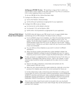
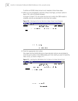
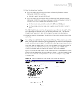
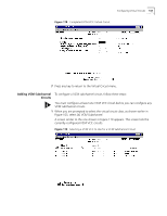
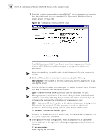
Configuring Virtual Circuits 145 Adding Voice To configure a VPC/VCC virtual circuit to connect data ports, follow these steps: Compression Module VCC Circuits You must configure at least one VCM VCC circuit before you can configure any VCM subchannel circuits. 1 When you are prompted to select the virtual circuit type, as shown earlier in Figure 105, enter 3 to create a VCM VCC circuit. A screen appears, listing the modules available to assign as side A of the virtual circuit, as shown in Figure 108. Figure 115 Selecting a Slot for Side A of a VCM VCC Virtual Circuit 2 Enter the number corresponding to the slot in which the Voice Compression module is installed (7 or 8) to assign the VCM to side A of the circuit. The Add Virtual Circuit screen displays the selected slot number and port type, lists the parameters you will enter for side A of the circuit, and prompts you to set the first parameter, as shown in Figure 116. 3 Follow the prompts that appear at the bottom of the screen, pressing [Enter] after each entry. Default values are listed in square brackets ([ ]) at the end of each prompt. Your settings are added to list of parameters at the top of the screen as you enter them. You must enter a setting for all the parameters for which you are prompted in order to add a circuit. Press [Delete] to back up to a previous selection. CAUTION: For voice compression circuits, select the Shaper Number corresponding to the maximum shaper value (typically Shaper Number 15). Make sure that Early Packet Discard is disabled (set to no) for voice compression circuits.
-
 1
1 -
2
-
3
-
4
-
5
-
6
-
7
-
8
-
9
-
10
-
11
-
12
-
13
-
14
-
15
-
16
-
17
-
18
-
19
-
20
-
21
-
22
-
23
-
24
-
25
-
26
-
27
-
28
-
29
-
30
-
31
-
32
-
33
-
34
-
35
-
36
-
37
-
38
-
39
-
40
-
41
-
42
-
43
-
44
-
45
-
46
-
47
-
48
-
49
-
50
-
51
-
52
-
53
-
54
-
55
-
56
-
57
-
58
-
59
-
60
-
61
-
62
-
63
-
64
-
65
-
66
-
67
-
68
-
69
-
70
-
71
-
72
-
73
-
74
-
75
-
76
-
77
-
78
-
79
-
80
-
81
-
82
-
83
-
84
-
85
-
86
-
87
-
88
-
89
-
90
-
91
-
92
-
93
-
94
-
95
-
96
-
97
-
98
-
99
-
100
-
101
-
102
-
103
-
104
-
105
-
106
-
107
-
108
-
109
-
110
-
111
-
112
-
113
-
114
-
115
-
116
-
117
-
118
-
119
-
120
-
121
-
122
-
123
-
124
-
125
-
126
-
127
-
128
-
129
-
130
-
131
-
132
-
133
-
134
-
135
-
136
-
137
-
138
-
139
-
140
-
141
-
142
-
143
-
144
-
145
-
146
-
147
-
148
-
149
-
150
-
151
-
 152
152 -
 153
153 -
 154
154 -
 155
155 -
 156
156 -
 157
157 -
 158
158 -
 159
159 -
 160
160 -
 161
161 -
 162
162 -
163
-
164
-
165
-
166
-
167
-
168
-
169
-
170
-
171
-
172
-
173
-
174
-
175
-
176
-
177
-
178
-
179
-
180
-
181
-
182
-
183
-
184
-
185
-
186
-
187
-
188
-
189
-
190
-
191
-
192
-
193
-
194
-
195
-
196
-
197
-
198
-
199
-
200
-
201
-
202
-
203
-
204
-
205
-
206
-
207
-
208
-
209
-
210
-
211
-
212
-
213
-
214
-
215
-
216
-
217
-
218
-
219
-
220
-
221
-
222
-
223
-
224
-
225
-
226
-
227
-
228
-
229
-
230
-
231
-
232
-
233
-
234
-
235
-
236
-
237
-
238
-
239
-
240
-
241
-
242
-
243
-
244
-
245
-
246
-
247
-
248
-
249
-
250
-
251
-
252
-
253
-
254
-
255
-
256
-
257
-
258
-
259
-
260
-
261
-
262
 |
 |
