3Com 3C63311 Reference Guide - Page 146
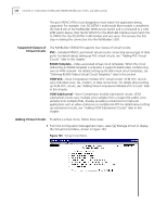
Supported Classes of Virtual Circuits, Adding Virtual Circuits, up VCM VCC circuits
 |
View all 3Com 3C63311 manuals
Add to My Manuals
Save this manual to your list of manuals |
Page 146 highlights
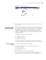
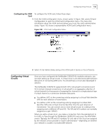
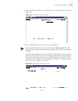
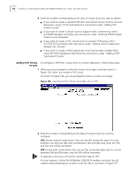
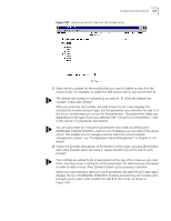
134 CHAPTER 4: CONFIGURING PATHBUILDER S330/S310 MODULES, PORTS, AND APPLICATIONS The port VPI/VCI ATM circuit designators must match the application being supported. For example, if an OC3/STM-1 multi-mode fiber module is installed in the Side B slot of the PathBuilder WAN Access Switch and is connected to a LAN ATM switch device, then the Rx VPI/VCI for the ATM LAN interface must match the Tx VPI/VCI for the OC3/STM-1 UNI module and vice versa. This ensures the first step in making the connection into the PathBuilder S330. Supported Classes of Virtual Circuits The PathBuilder S330/S310 supports four classes of virtual circuits; PVC-Standard VP/VCC permanent virtual circuits connecting various type of data ports. For details about setting up PVC virtual circuits, see "Adding PVC Virtual Circuits" later in this chapter. RS366 Template-Video-associated virtual circuit templates. When the circuit defined by an RS366 template is activated, it supports dialed video conferencing over an ATM network. For details setting up RS-366 virtual circuit templates, see "Defining RS366 (Video) Virtual Circuit Templates" later in this section. VCM VCC-Voice Compression module VCC virtual circuits. VCM VCC circuits carry individual voice, fax, modem, or data connections. For details about setting up VCM VCC circuits, see "Adding Voice Compression Module VCC Circuits" later in this chapter. VCM Subchannel-Voice Compression module subchannel circuits. VCM subchannel circuits carry multiple voice samples from a single DS0 and/or voice samples from multiple DS0s, thereby providing connections for high-rate applications such as video conference or multiple-link PPP. For details about setting up subchannel circuits, see "Adding VCM Subchannel Circuits" later in this chapter. Adding Virtual Circuits To define a virtual circuit, follow these steps: 1 From the Configuration Management menu, select [2] Manage Circuit to display the Virtual Circuit Menu, shown in Figure 103. Figure 103 Virtual Circuit Menu
-
 1
1 -
2
-
3
-
4
-
5
-
6
-
7
-
8
-
9
-
10
-
11
-
12
-
13
-
14
-
15
-
16
-
17
-
18
-
19
-
20
-
21
-
22
-
23
-
24
-
25
-
26
-
27
-
28
-
29
-
30
-
31
-
32
-
33
-
34
-
35
-
36
-
37
-
38
-
39
-
40
-
41
-
42
-
43
-
44
-
45
-
46
-
47
-
48
-
49
-
50
-
51
-
52
-
53
-
54
-
55
-
56
-
57
-
58
-
59
-
60
-
61
-
62
-
63
-
64
-
65
-
66
-
67
-
68
-
69
-
70
-
71
-
72
-
73
-
74
-
75
-
76
-
77
-
78
-
79
-
80
-
81
-
82
-
83
-
84
-
85
-
86
-
87
-
88
-
89
-
90
-
91
-
92
-
93
-
94
-
95
-
96
-
97
-
98
-
99
-
100
-
101
-
102
-
103
-
104
-
105
-
106
-
107
-
108
-
109
-
110
-
111
-
112
-
113
-
114
-
115
-
116
-
117
-
118
-
119
-
120
-
121
-
122
-
123
-
124
-
125
-
126
-
127
-
128
-
129
-
130
-
131
-
132
-
133
-
134
-
135
-
136
-
137
-
138
-
139
-
140
-
 141
141 -
 142
142 -
 143
143 -
 144
144 -
 145
145 -
 146
146 -
 147
147 -
 148
148 -
 149
149 -
 150
150 -
 151
151 -
152
-
153
-
154
-
155
-
156
-
157
-
158
-
159
-
160
-
161
-
162
-
163
-
164
-
165
-
166
-
167
-
168
-
169
-
170
-
171
-
172
-
173
-
174
-
175
-
176
-
177
-
178
-
179
-
180
-
181
-
182
-
183
-
184
-
185
-
186
-
187
-
188
-
189
-
190
-
191
-
192
-
193
-
194
-
195
-
196
-
197
-
198
-
199
-
200
-
201
-
202
-
203
-
204
-
205
-
206
-
207
-
208
-
209
-
210
-
211
-
212
-
213
-
214
-
215
-
216
-
217
-
218
-
219
-
220
-
221
-
222
-
223
-
224
-
225
-
226
-
227
-
228
-
229
-
230
-
231
-
232
-
233
-
234
-
235
-
236
-
237
-
238
-
239
-
240
-
241
-
242
-
243
-
244
-
245
-
246
-
247
-
248
-
249
-
250
-
251
-
252
-
253
-
254
-
255
-
256
-
257
-
258
-
259
-
260
-
261
-
262
 |
 |
