3Com 3C63311 Reference Guide - Page 140
Configuring the CBR Card, shows the CBR E1 Card Configuration menu. The CBR t1-DSX Card - driver
 |
View all 3Com 3C63311 manuals
Add to My Manuals
Save this manual to your list of manuals |
Page 140 highlights
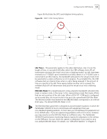
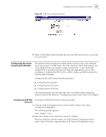
128 CHAPTER 4: CONFIGURING PATHBUILDER S330/S310 MODULES, PORTS, AND APPLICATIONS Dial Timer-The amount of time, in seconds, after which dialing is assumed to be ended if no further digits have been received: 6-60. This parameter applies to the video dial feature. The RS-366 specification does not require all calls to be ended with the EON (End of Number) digit. If no EON is available, the CBR software uses the Dial Timer to determine when dialing is complete. The CBR software resets the timer each time a digit is received. When the timer expires, the dialing is assumed to be completed, and the RS-366 driver forwards the call to the call handling task for further processing. When used alone, the CBR V.35 interface is used in the lease line environment, and all of the interface signals are forced to on. When used with RS-366, the CBR V.35 interface is used in a switched environment. The DSR and CTS&DCD options allow you to emulate the switched environment by specifying that certain interface signals should go off in alarm conditions. DSR Option-Specifies the behavior of the DSR interface signal: Forced On-Force the DSR signal to on in all conditions. Follow DTR-Direct the DSR signal to follow the DTR signal. Toggle-Toggle the DSR signal off for three seconds and then to on after the DSC goes off. CTS&DCD Option-Specifies the behavior of the CTS and DCD interface signals: Forced On-Force the CTS and DCD signals to on in all conditions. Follow DTR-Direct the CTS and DCD signals to follow the DTR signal. Follow DTR & DSC-Direct the CTS and DCD signals to follow the DTR and DSC signals. Admin. Status-Administrative status: In Service or Out of Service. Configuring the CBR The only type of configuration you can perform on the T1/E1 UNI card is to put it Card in service or out of service. To put the T1/E1 UNI card in service or out of service, follow these steps: 1 From the Configuration Management menu, select [1] Manage Card. 2 From the List Card menu, shown earlier in Figure 51, select [7] CBR. The CBR T1-DSX or CBR E1 Configuration Selection menu appears, as shown earlier in Figure 93. 3 Select [5] Card Configuration to display the CBR Card Configuration menu. Figure 98 shows the CBR E1 Card Configuration menu. The CBR t1-DSX Card Configuration menu is the same.
-
 1
1 -
2
-
3
-
4
-
5
-
6
-
7
-
8
-
9
-
10
-
11
-
12
-
13
-
14
-
15
-
16
-
17
-
18
-
19
-
20
-
21
-
22
-
23
-
24
-
25
-
26
-
27
-
28
-
29
-
30
-
31
-
32
-
33
-
34
-
35
-
36
-
37
-
38
-
39
-
40
-
41
-
42
-
43
-
44
-
45
-
46
-
47
-
48
-
49
-
50
-
51
-
52
-
53
-
54
-
55
-
56
-
57
-
58
-
59
-
60
-
61
-
62
-
63
-
64
-
65
-
66
-
67
-
68
-
69
-
70
-
71
-
72
-
73
-
74
-
75
-
76
-
77
-
78
-
79
-
80
-
81
-
82
-
83
-
84
-
85
-
86
-
87
-
88
-
89
-
90
-
91
-
92
-
93
-
94
-
95
-
96
-
97
-
98
-
99
-
100
-
101
-
102
-
103
-
104
-
105
-
106
-
107
-
108
-
109
-
110
-
111
-
112
-
113
-
114
-
115
-
116
-
117
-
118
-
119
-
120
-
121
-
122
-
123
-
124
-
125
-
126
-
127
-
128
-
129
-
130
-
131
-
132
-
133
-
134
-
 135
135 -
 136
136 -
 137
137 -
 138
138 -
 139
139 -
 140
140 -
 141
141 -
 142
142 -
 143
143 -
 144
144 -
 145
145 -
146
-
147
-
148
-
149
-
150
-
151
-
152
-
153
-
154
-
155
-
156
-
157
-
158
-
159
-
160
-
161
-
162
-
163
-
164
-
165
-
166
-
167
-
168
-
169
-
170
-
171
-
172
-
173
-
174
-
175
-
176
-
177
-
178
-
179
-
180
-
181
-
182
-
183
-
184
-
185
-
186
-
187
-
188
-
189
-
190
-
191
-
192
-
193
-
194
-
195
-
196
-
197
-
198
-
199
-
200
-
201
-
202
-
203
-
204
-
205
-
206
-
207
-
208
-
209
-
210
-
211
-
212
-
213
-
214
-
215
-
216
-
217
-
218
-
219
-
220
-
221
-
222
-
223
-
224
-
225
-
226
-
227
-
228
-
229
-
230
-
231
-
232
-
233
-
234
-
235
-
236
-
237
-
238
-
239
-
240
-
241
-
242
-
243
-
244
-
245
-
246
-
247
-
248
-
249
-
250
-
251
-
252
-
253
-
254
-
255
-
256
-
257
-
258
-
259
-
260
-
261
-
262
 |
 |
