3Com 3C63311 Reference Guide - Page 166
FECN to EFCI Mapping, Direct, Always 0, DFA VPI, DFA VCI Range
 |
View all 3Com 3C63311 manuals
Add to My Manuals
Save this manual to your list of manuals |
Page 166 highlights
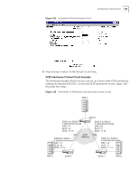
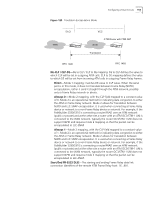
154 CHAPTER 4: CONFIGURING PATHBUILDER S330/S310 MODULES, PORTS, AND APPLICATIONS FECN to EFCI Mapping-Defines the mapping of FECN incoming on Frame Relay to the outgoing ATM cell PTI congestion indicator. Direct-Mode 1 mapping; matches FECN to the PTI CN bit. When the serial port is in this mode, it does not translate between Frame Relay (NLPID) encapsulation, rather it sends it straight through the ATM network, possibly onto a Frame Relay network or device. Always 0-Mode 2 mapping. This option sets the EFCI field to 'congestion not experienced.' Mode 2 is an operational method for indicating data congestion to either the ATM or Frame Relay network. Mode 2 allows for translation between NLPID and LLC-SNAP encapsulation. It is used when connecting a Frame Relay device or network to a non-Frame Relay device or network. For example, if the PathBuilder S330 is connecting a router/FRAD over an ATM network (public or private) and at the other site a router with an ATM OC3/STM-1 UNI is connected to the WAN network, typically the router OC3/STM-1 UNI does not support NLPID and requires mode 2 mapping so that the packet can be encapsulated to LLC-SNAP. DXI Virtual Circuit Parameters If the serial port is configured as a DXI port, you must set the following virtual circuit parameters in addition to the common Shaper Number, Priority, and Early Packet Discard parameters: (DFA) VPI-The virtual path indicator (VPI) number corresponding to the DFA field: 0...15. This parameter defines the selected VPI for Mapping to/from the Port card (Router) to the trunk. (DFA) VCI-The virtual channel indicator (VCI) number corresponding to the DFA field: 0...63. This parameter defines the selected VPI for Mapping to/from the Port card (Router) to the trunk. (DFA) VCI Range-The DXI virtual channel indicator range: 1...32. This parameter defines the range of VCs starting from the one selected, in twos. and allows quick input of multiple VCs. SDLC Virtual Circuit Parameters If the serial port is configured as a SDLC port, you simply set the common Shaper Number, Priority, and Early Packet Discard parameters. Ethernet Port Virtual Circuit Parameters For Ethernet port virtual circuits you simply set the common Shaper Number, Priority, and Early Packet Discard parameters. CBR Module Virtual Circuit Parameters The parameters that appear on the Add Virtual Circuit screen when you select the CBR module to be a side of a circuit vary, depending on whether you select the V.35 port or one of the T1/E1 ports. In addition to the common Shaper Number, Priority, and Early Packet Discard parameters, you must set the following parameters: Port-The CBR module port number.
-
 1
1 -
2
-
3
-
4
-
5
-
6
-
7
-
8
-
9
-
10
-
11
-
12
-
13
-
14
-
15
-
16
-
17
-
18
-
19
-
20
-
21
-
22
-
23
-
24
-
25
-
26
-
27
-
28
-
29
-
30
-
31
-
32
-
33
-
34
-
35
-
36
-
37
-
38
-
39
-
40
-
41
-
42
-
43
-
44
-
45
-
46
-
47
-
48
-
49
-
50
-
51
-
52
-
53
-
54
-
55
-
56
-
57
-
58
-
59
-
60
-
61
-
62
-
63
-
64
-
65
-
66
-
67
-
68
-
69
-
70
-
71
-
72
-
73
-
74
-
75
-
76
-
77
-
78
-
79
-
80
-
81
-
82
-
83
-
84
-
85
-
86
-
87
-
88
-
89
-
90
-
91
-
92
-
93
-
94
-
95
-
96
-
97
-
98
-
99
-
100
-
101
-
102
-
103
-
104
-
105
-
106
-
107
-
108
-
109
-
110
-
111
-
112
-
113
-
114
-
115
-
116
-
117
-
118
-
119
-
120
-
121
-
122
-
123
-
124
-
125
-
126
-
127
-
128
-
129
-
130
-
131
-
132
-
133
-
134
-
135
-
136
-
137
-
138
-
139
-
140
-
141
-
142
-
143
-
144
-
145
-
146
-
147
-
148
-
149
-
150
-
151
-
152
-
153
-
154
-
155
-
156
-
157
-
158
-
159
-
160
-
 161
161 -
 162
162 -
 163
163 -
 164
164 -
 165
165 -
 166
166 -
 167
167 -
 168
168 -
 169
169 -
 170
170 -
 171
171 -
172
-
173
-
174
-
175
-
176
-
177
-
178
-
179
-
180
-
181
-
182
-
183
-
184
-
185
-
186
-
187
-
188
-
189
-
190
-
191
-
192
-
193
-
194
-
195
-
196
-
197
-
198
-
199
-
200
-
201
-
202
-
203
-
204
-
205
-
206
-
207
-
208
-
209
-
210
-
211
-
212
-
213
-
214
-
215
-
216
-
217
-
218
-
219
-
220
-
221
-
222
-
223
-
224
-
225
-
226
-
227
-
228
-
229
-
230
-
231
-
232
-
233
-
234
-
235
-
236
-
237
-
238
-
239
-
240
-
241
-
242
-
243
-
244
-
245
-
246
-
247
-
248
-
249
-
250
-
251
-
252
-
253
-
254
-
255
-
256
-
257
-
258
-
259
-
260
-
261
-
262
 |
 |
