3Com 3C63311 Reference Guide - Page 95
Viewing MCPU Configuration Information, Configuring MCPU Shapers
 |
View all 3Com 3C63311 manuals
Add to My Manuals
Save this manual to your list of manuals |
Page 95 highlights
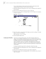
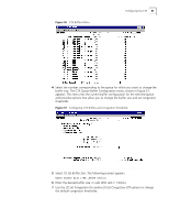
Figure 52 MCPU Configuration Menu Configuring the Management CPU 83 Viewing MCPU Configuration Information To view configuration information for the management CPU: From the MCPU Configuration menu, select [1] Card Configuration to open the Management Processor Configuration screen. This screen displays the following CPU configuration information: n Hardware revision n Serial number n Status (In Service or Out of Service) Configuring MCPU Shapers The PathBuilder S330/S310 supports three MCPU shapers parameters: n Peak Cell Rate (PCR)-The maximum rate that can be passed. n Sustained Cell Rate (SCR)-The maximum average rate that a bursty, on-off traffic source can send; used in conjunction with maximum burst size. n Maximum Burst Size (MBS)-The maximum number of cells that can be sent at the peak rate; used in conjunction with sustained cell rate. Using the MCPU Shapers screen, shown below in Figure 53, you can configure up to 15 shapers. The values that you set for the shapers on this screen are the values that are then available for the Shaper Number parameter that you set when you configure certain types of virtual circuits. See "Common VIrtual Circuit Parameters" later in this chapter for details. How you configure the MCPU shapers depends on the type of service you have. n If you have a peak rate service: n Set the peak rate at the maximum allowable value. n Set the sustained cell rate at the same rate as the peak rate. n If you have a sustained rate service: n Set the peak rate at the line rate (for example 45Mbps for a DS3 line). n Set the sustained cell rate and maximum burst rate at the values given to you by your service provider.
-
 1
1 -
2
-
3
-
4
-
5
-
6
-
7
-
8
-
9
-
10
-
11
-
12
-
13
-
14
-
15
-
16
-
17
-
18
-
19
-
20
-
21
-
22
-
23
-
24
-
25
-
26
-
27
-
28
-
29
-
30
-
31
-
32
-
33
-
34
-
35
-
36
-
37
-
38
-
39
-
40
-
41
-
42
-
43
-
44
-
45
-
46
-
47
-
48
-
49
-
50
-
51
-
52
-
53
-
54
-
55
-
56
-
57
-
58
-
59
-
60
-
61
-
62
-
63
-
64
-
65
-
66
-
67
-
68
-
69
-
70
-
71
-
72
-
73
-
74
-
75
-
76
-
77
-
78
-
79
-
80
-
81
-
82
-
83
-
84
-
85
-
86
-
87
-
88
-
89
-
 90
90 -
 91
91 -
 92
92 -
 93
93 -
 94
94 -
 95
95 -
 96
96 -
 97
97 -
 98
98 -
 99
99 -
 100
100 -
101
-
102
-
103
-
104
-
105
-
106
-
107
-
108
-
109
-
110
-
111
-
112
-
113
-
114
-
115
-
116
-
117
-
118
-
119
-
120
-
121
-
122
-
123
-
124
-
125
-
126
-
127
-
128
-
129
-
130
-
131
-
132
-
133
-
134
-
135
-
136
-
137
-
138
-
139
-
140
-
141
-
142
-
143
-
144
-
145
-
146
-
147
-
148
-
149
-
150
-
151
-
152
-
153
-
154
-
155
-
156
-
157
-
158
-
159
-
160
-
161
-
162
-
163
-
164
-
165
-
166
-
167
-
168
-
169
-
170
-
171
-
172
-
173
-
174
-
175
-
176
-
177
-
178
-
179
-
180
-
181
-
182
-
183
-
184
-
185
-
186
-
187
-
188
-
189
-
190
-
191
-
192
-
193
-
194
-
195
-
196
-
197
-
198
-
199
-
200
-
201
-
202
-
203
-
204
-
205
-
206
-
207
-
208
-
209
-
210
-
211
-
212
-
213
-
214
-
215
-
216
-
217
-
218
-
219
-
220
-
221
-
222
-
223
-
224
-
225
-
226
-
227
-
228
-
229
-
230
-
231
-
232
-
233
-
234
-
235
-
236
-
237
-
238
-
239
-
240
-
241
-
242
-
243
-
244
-
245
-
246
-
247
-
248
-
249
-
250
-
251
-
252
-
253
-
254
-
255
-
256
-
257
-
258
-
259
-
260
-
261
-
262
 |
 |
