Dell OptiPlex GX260 User Guide - Page 32
Inside Your Computer, Small Form-Factor Computer - sound card
 |
View all Dell OptiPlex GX260 manuals
Add to My Manuals
Save this manual to your list of manuals |
Page 32 highlights
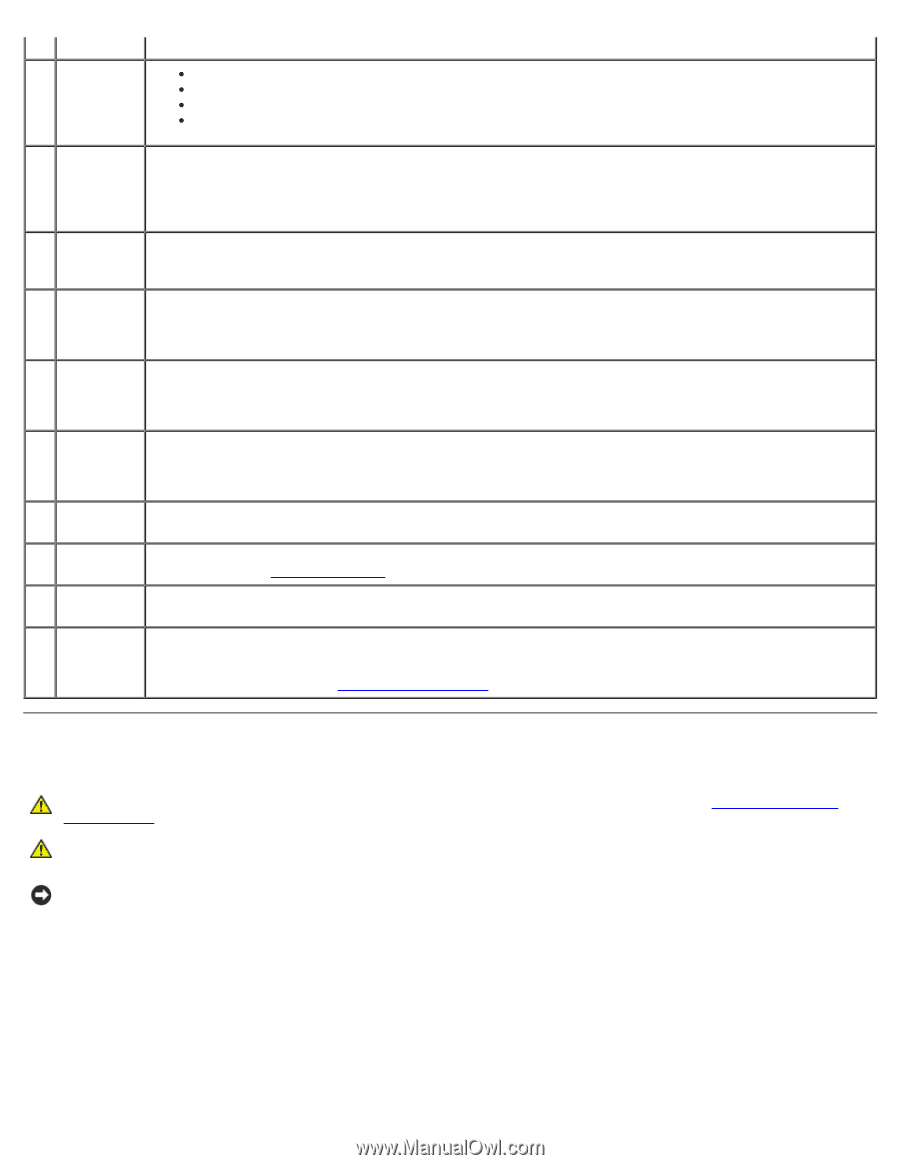
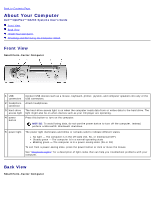
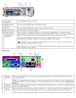
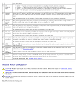
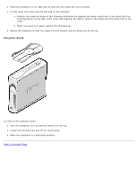
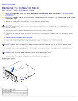
4 link integrity light your hard drive. Green - A good connection exists between a 10-Mbps network and the computer. Orange - A good connection exists between a 100-Mbps network and the computer. Yellow - A good connection exists between a 1,000-Mbps (1-Gbps) network and the computer. Off - The computer is not detecting a physical connection to the network. 5 network adapter Attach the UTP cable to an RJ45 jack wall plate or to an RJ45 port on a UTP concentrator or hub and press the other end of the UTP cable into the network adapter connector until the cable snaps securely into place. 6 network activity light Dell recommends the use of Category 5 wiring and connectors for our customers' networks. The yellow light flashes when the computer is transmitting or receiving network data. A high volume of network traffic may make this light appear to be in a steady "on" state. 7 line-in Use the green line-out connector (available on computers with integrated sound) to attach headphones connector and most speakers with integrated amplifiers. On computers with a sound card, the line-out connector is on the card. 8 line-out Use the blue line-in connector (available on computers with integrated sound) to attach a record/playback connector device such as a cassette player, CD player, or VCR. On computers with a sound card, the line-in connector is on the card. 9 microphone Use the pink microphone connector (available on computers with integrated sound) to attach a personal connector computer microphone for voice or musical input into a sound or telephony program. On computers with a sound card, the microphone connector is on the card. 10 USB Connect USB devices such as a mouse, keyboard, printer, joystick, and computer speakers into any of the connectors USB connectors. 11 diagnostic Use the lights to help you troubleshoot a computer problem based on the diagnostic code. For more lights information, see "Diagnostic Lights." 12 video Plug the cable from your VGA-compatible monitor into the blue connector. connector 13 serial Connect a serial device, such as a handheld device, to the serial connector. If you have a second serial connector connector card installed, you can connect a second device to that connector. For more information, see "System Setup Options." Inside Your Computer CAUTION: Before you begin any of the procedures in this section, follow the steps in "CAUTION: Safety Instructions." CAUTION: To avoid electrical shock, always unplug your computer from the electrical outlet before opening the cover. NOTICE: Be careful when opening the computer cover to ensure that you do not accidently disconnect cables from the system board. Small Form-Factor Computer
-
 1
1 -
2
-
3
-
4
-
5
-
6
-
7
-
8
-
9
-
10
-
11
-
12
-
13
-
14
-
15
-
16
-
17
-
18
-
19
-
20
-
21
-
22
-
23
-
24
-
25
-
26
-
 27
27 -
 28
28 -
 29
29 -
 30
30 -
 31
31 -
 32
32 -
 33
33 -
 34
34 -
 35
35 -
 36
36 -
 37
37 -
38
-
39
-
40
-
41
-
42
-
43
-
44
-
45
-
46
-
47
-
48
-
49
-
50
-
51
-
52
-
53
-
54
-
55
-
56
-
57
-
58
-
59
-
60
-
61
-
62
-
63
-
64
-
65
-
66
-
67
-
68
-
69
-
70
-
71
-
72
-
73
-
74
-
75
-
76
-
77
-
78
-
79
-
80
-
81
-
82
-
83
-
84
-
85
-
86
-
87
-
88
-
89
-
90
-
91
-
92
-
93
-
94
-
95
-
96
-
97
-
98
-
99
-
100
-
101
-
102
-
103
-
104
-
105
-
106
-
107
-
108
-
109
-
110
-
111
-
112
-
113
-
114
-
115
-
116
-
117
-
118
-
119
-
120
-
121
-
122
-
123
-
124
-
125
-
126
-
127
-
128
-
129
-
130
-
131
-
132
-
133
-
134
-
135
-
136
-
137
-
138
-
139
-
140
-
141
-
142
-
143
-
144
-
145
-
146
-
147
-
148
-
149
-
150
-
151
-
152
-
153
-
154
-
155
-
156
-
157
-
158
-
159
-
160
-
161
-
162
-
163
-
164
-
165
-
166
-
167
-
168
-
169
-
170
-
171
-
172
-
173
-
174
-
175
-
176
-
177
-
178
-
179
-
180
-
181
-
182
-
183
-
184
-
185
-
186
-
187
-
188
-
189
-
190
-
191
-
192
-
193
-
194
-
195
-
196
-
197
-
198
-
199
-
200
-
201
-
202
-
203
-
204
-
205
-
206
-
207
-
208
-
209
-
210
-
211
-
212
-
213
-
214
-
215
-
216
-
217
-
218
-
219
-
220
-
221
-
222
-
223
-
224
-
225
-
226
-
227
-
228
-
229
-
230
-
231
-
232
-
233
-
234
-
235
 |
 |