Dell OptiPlex GX260 User Guide - Page 74
Telephony Applications Programming Interface (TAPI): Dell OptiPlex GX260 Systems User's Guide
 |
View all Dell OptiPlex GX260 manuals
Add to My Manuals
Save this manual to your list of manuals |
Page 74 highlights
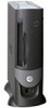
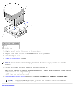
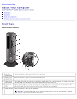
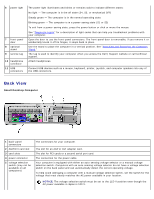
Back to Contents Page Telephony Applications Programming Interface (TAPI) Dell™ OptiPlex™ GX260 Systems User's Guide NOTE: See the documentation that came with the TAPI-compliant card for more information on using TAPI devices and to verify that the card works with your computer. Your computer supports TAPI-compliant modem cards using the standard TAPI connector (the green connector labeled MODEM or TELEPHONY). If your modem supports voice features, you can connect your modem to the TAPI connector and then use your audio speakers and microphone as an answering machine or speakerphone. The microphone carries your voice into the computer and then through the TAPI system board connector to your modem card. The caller's voice enters through the modem card to the TAPI system board connector and then out to the speakers. You can also use this configuration to record and play audio files over the telephone by using third-party software. CAUTION: Before you begin any of the procedures in this section, follow the steps in "CAUTION: Safety Instructions." CAUTION: To guard against electrical shock, always unplug your computer from the electrical outlet before opening the cover. Installing a TAPI-Compliant Modem Card 1. Perform an orderly computer shutdown using the operating system menu. NOTICE: To disconnect a network cable, first unplug the cable from your computer, and then unplug it from the network wall jack. 2. Turn off any attached devices and disconnect them from their electrical outlets. 3. Disconnect the computer power cable from the wall outlet, and then press the power button to ground the system board. 4. If your computer has a stand and it is attached, remove the stand. 5. Open the computer cover. 6. Install the TAPI-compliant modem card. a. Connect the 4-pin TAPI cable to the TAPI system board connector. To locate the TAPI connector on the system board, see "System Board Components." b. Connect the other end of the cable to the TAPI connector on the modem card. To locate the TAPI connector on the card, see the manufacturer's documentation. 7. Close the computer cover. 8. Reconnect the computer and devices to electrical outlets, and turn them on. If enabled, the chassis intrusion detector causes the following message to appear on the screen at the next computer start - up: ALERT! Cover was previously removed. 9. Reset the chassis intrusion detector by changing Chassis Intrusion to Enabled or Enabled-Silent. NOTE: If a setup password has been assigned by someone else, contact your network administrator for information on resetting the chassis intrusion detector.
-
 1
1 -
2
-
3
-
4
-
5
-
6
-
7
-
8
-
9
-
10
-
11
-
12
-
13
-
14
-
15
-
16
-
17
-
18
-
19
-
20
-
21
-
22
-
23
-
24
-
25
-
26
-
27
-
28
-
29
-
30
-
31
-
32
-
33
-
34
-
35
-
36
-
37
-
38
-
39
-
40
-
41
-
42
-
43
-
44
-
45
-
46
-
47
-
48
-
49
-
50
-
51
-
52
-
53
-
54
-
55
-
56
-
57
-
58
-
59
-
60
-
61
-
62
-
63
-
64
-
65
-
66
-
67
-
68
-
 69
69 -
 70
70 -
 71
71 -
 72
72 -
 73
73 -
 74
74 -
 75
75 -
 76
76 -
 77
77 -
 78
78 -
 79
79 -
80
-
81
-
82
-
83
-
84
-
85
-
86
-
87
-
88
-
89
-
90
-
91
-
92
-
93
-
94
-
95
-
96
-
97
-
98
-
99
-
100
-
101
-
102
-
103
-
104
-
105
-
106
-
107
-
108
-
109
-
110
-
111
-
112
-
113
-
114
-
115
-
116
-
117
-
118
-
119
-
120
-
121
-
122
-
123
-
124
-
125
-
126
-
127
-
128
-
129
-
130
-
131
-
132
-
133
-
134
-
135
-
136
-
137
-
138
-
139
-
140
-
141
-
142
-
143
-
144
-
145
-
146
-
147
-
148
-
149
-
150
-
151
-
152
-
153
-
154
-
155
-
156
-
157
-
158
-
159
-
160
-
161
-
162
-
163
-
164
-
165
-
166
-
167
-
168
-
169
-
170
-
171
-
172
-
173
-
174
-
175
-
176
-
177
-
178
-
179
-
180
-
181
-
182
-
183
-
184
-
185
-
186
-
187
-
188
-
189
-
190
-
191
-
192
-
193
-
194
-
195
-
196
-
197
-
198
-
199
-
200
-
201
-
202
-
203
-
204
-
205
-
206
-
207
-
208
-
209
-
210
-
211
-
212
-
213
-
214
-
215
-
216
-
217
-
218
-
219
-
220
-
221
-
222
-
223
-
224
-
225
-
226
-
227
-
228
-
229
-
230
-
231
-
232
-
233
-
234
-
235
 |
 |