Dell OptiPlex GX260 User Guide - Page 68
Microprocessor: Dell OptiPlex GX260 Systems User's Guide, Heat Sink/Blower Assembly Removal
 |
View all Dell OptiPlex GX260 manuals
Add to My Manuals
Save this manual to your list of manuals |
Page 68 highlights
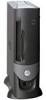
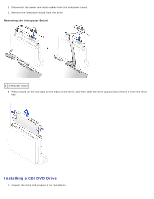
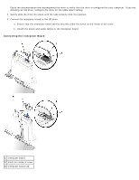
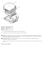
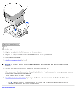
Back to Contents Page Microprocessor Dell™ OptiPlex™ GX260 Systems User's Guide CAUTION: Before you begin any of the procedures in this section, follow the steps in "CAUTION: Safety Instructions." CAUTION: To guard against electrical shock, always unplug your computer from the electrical outlet before opening the cover. 1. Perform an orderly computer shutdown using the operating system menu. NOTICE: To disconnect a network cable, first unplug the cable from your computer, and then unplug it from the network wall jack. 2. Turn off any attached devices and disconnect them from their electrical outlets. 3. Disconnect the computer power cable from the wall outlet, and then press the power button to ground the system board. 4. Remove the computer stand, if it is attached. 5. Open the computer cover. 6. Disconnect the cooling fan power cable from the FAN connector on the system board. 7. Disconnect the 12-volt power cable from the 12VPOWER connector on the system board. 8. Remove the heat sink/blower assembly. a. The heat sink is attached to the blower. Press and lower the green lever on the retention mechanism until it is parallel to the system board. b. Gently rock the heat sink and then slightly twist it as you lift it from the microprocessor. NOTICE: Lay the heat sink down with the thermal solution facing upward. Heat Sink/Blower Assembly Removal
-
 1
1 -
2
-
3
-
4
-
5
-
6
-
7
-
8
-
9
-
10
-
11
-
12
-
13
-
14
-
15
-
16
-
17
-
18
-
19
-
20
-
21
-
22
-
23
-
24
-
25
-
26
-
27
-
28
-
29
-
30
-
31
-
32
-
33
-
34
-
35
-
36
-
37
-
38
-
39
-
40
-
41
-
42
-
43
-
44
-
45
-
46
-
47
-
48
-
49
-
50
-
51
-
52
-
53
-
54
-
55
-
56
-
57
-
58
-
59
-
60
-
61
-
62
-
 63
63 -
 64
64 -
 65
65 -
 66
66 -
 67
67 -
 68
68 -
 69
69 -
 70
70 -
 71
71 -
 72
72 -
 73
73 -
74
-
75
-
76
-
77
-
78
-
79
-
80
-
81
-
82
-
83
-
84
-
85
-
86
-
87
-
88
-
89
-
90
-
91
-
92
-
93
-
94
-
95
-
96
-
97
-
98
-
99
-
100
-
101
-
102
-
103
-
104
-
105
-
106
-
107
-
108
-
109
-
110
-
111
-
112
-
113
-
114
-
115
-
116
-
117
-
118
-
119
-
120
-
121
-
122
-
123
-
124
-
125
-
126
-
127
-
128
-
129
-
130
-
131
-
132
-
133
-
134
-
135
-
136
-
137
-
138
-
139
-
140
-
141
-
142
-
143
-
144
-
145
-
146
-
147
-
148
-
149
-
150
-
151
-
152
-
153
-
154
-
155
-
156
-
157
-
158
-
159
-
160
-
161
-
162
-
163
-
164
-
165
-
166
-
167
-
168
-
169
-
170
-
171
-
172
-
173
-
174
-
175
-
176
-
177
-
178
-
179
-
180
-
181
-
182
-
183
-
184
-
185
-
186
-
187
-
188
-
189
-
190
-
191
-
192
-
193
-
194
-
195
-
196
-
197
-
198
-
199
-
200
-
201
-
202
-
203
-
204
-
205
-
206
-
207
-
208
-
209
-
210
-
211
-
212
-
213
-
214
-
215
-
216
-
217
-
218
-
219
-
220
-
221
-
222
-
223
-
224
-
225
-
226
-
227
-
228
-
229
-
230
-
231
-
232
-
233
-
234
-
235
 |
 |