Dell PowerConnect B-DCX4S Hardware Reference Guide
Dell PowerConnect B-DCX4S Manual
 |
View all Dell PowerConnect B-DCX4S manuals
Add to My Manuals
Save this manual to your list of manuals |
Dell PowerConnect B-DCX4S manual content summary:
- Dell PowerConnect B-DCX4S | Hardware Reference Guide - Page 1
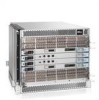
53-1001808-01 January 31, 2010 PowerConnect B-DCX-4S Backbone Hardware Reference Manual 53-1001808-01 *53-1001808-01* - Dell PowerConnect B-DCX4S | Hardware Reference Guide - Page 2
refer to either the entities claiming the marks and names or their products. Dell Inc. disclaims any proprietary interest in trademarks and trade names other than its own. Regulatory Model Codes: Brocade DCX-4S, Brocade DCX ii PowerConnect B-DCX-4S Backbone Hardware Reference Manual 53-1001808-01 - Dell PowerConnect B-DCX4S | Hardware Reference Guide - Page 3
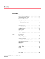
side of the PowerConnect B-DCX-4S 5 PowerConnect B-DCX-4S blades 5 High availability 6 Reliability 7 Serviceability 7 Software features 8 Security 8 Network manageability 9 Chapter 2 Installation In this chapter 11 PowerConnect B-DCX-4S Backbone Hardware Reference Manual iii 53-1001808 - Dell PowerConnect B-DCX4S | Hardware Reference Guide - Page 4
switch blade (CR4S-8 38 Determining the status of a power supply 39 Determining the status of a blower assembly 40 Determining the status of a WWN card 41 Removal and Replacement Procedures (RRPs) In this chapter 43 iv PowerConnect B-DCX-4S Backbone Hardware Reference Manual 53-1001808-01 - Dell PowerConnect B-DCX4S | Hardware Reference Guide - Page 5
core switch blade (CR4S-8 58 RRP: Power supply 59 Time and items required 59 Identification 59 Removing a power supply 59 Replacing a power supply 60 RRP: Blower assembly 60 Time : Inter-chassis link (ICL) cables 66 PowerConnect B-DCX-4S Backbone Hardware Reference Manual v 53-1001808-01 - Dell PowerConnect B-DCX4S | Hardware Reference Guide - Page 6
Environmental requirements 89 Fibre Channel port specifications 90 Power specifications 90 Power cords 91 Power-cord notice 94 Power-cord notice (Japan, Denan 94 Data transmission FA4-18 blade 101 FR4-18i blade 101 vi PowerConnect B-DCX-4S Backbone Hardware Reference Manual 53-1001808-01 - Dell PowerConnect B-DCX4S | Hardware Reference Guide - Page 7
Diagnostics and Troubleshooting In this appendix 105 Introduction 105 Obtaining chassis and component status 106 Interpreting POST and boot results 106 POST 106 Boot 107 Diagnostics 107 Troubleshooting 108 Port Numbering Template PowerConnect B-DCX-4S Backbone Hardware Reference Manual vii - Dell PowerConnect B-DCX4S | Hardware Reference Guide - Page 8
viii PowerConnect B-DCX-4S Backbone Hardware Reference Manual 53-1001808-01 - Dell PowerConnect B-DCX4S | Hardware Reference Guide - Page 9
is a hardware reference manual written for system administrators and technicians experienced with networking, Fibre Channel, and SAN technologies to help them install, set up, configure, operate, maintain, and troubleshoot the PowerConnect B-DCX-4S Backbone ("PowerConnect B-DCX-4S"). This document - Dell PowerConnect B-DCX4S | Hardware Reference Guide - Page 10
Supported hardware and software This document includes information specific to the PowerConnect B-DCX-4S running Brocade Fabric OS version 6.3. What's new in this document The control blade replacement instructions have been updated. The Setting IP Addresses procedure has been updated. Added power - Dell PowerConnect B-DCX4S | Hardware Reference Guide - Page 11
this guide are presented in mixed lettercase: for example, switchShow. In actual examples, command lettercase is often all lowercase. Otherwise, this manual specifically Networking Industry Association online dictionary at: PowerConnect B-DCX-4S Backbone Hardware Reference Manual xi 53-1001808-01 - Dell PowerConnect B-DCX4S | Hardware Reference Guide - Page 12
the Brocade Web site at: http://www.brocade.com/products-solutions/products/index.page For additional Brocade documentation, visit the Brocade Web site: http://www.brocade.com Fibre Channel Industry Association Web site: xii PowerConnect B-DCX-4S Backbone Hardware Reference Manual 53-1001808-01 - Dell PowerConnect B-DCX4S | Hardware Reference Guide - Page 13
• Technical Support contract number, if applicable • PowerConnect B-DCX-4S model • PowerConnect B-DCX-4S operating system version • Error numbers and messages received • supportSave command output • Detailed description of the problem and specific questions • Description of any troubleshooting steps - Dell PowerConnect B-DCX4S | Hardware Reference Guide - Page 14
to: [email protected] Provide the title and version number of the document and as much detail as possible about your comment, including the topic heading and page number and your suggestions for improvement. xiv PowerConnect B-DCX-4S Backbone Hardware Reference Manual 53-1001808-01 - Dell PowerConnect B-DCX4S | Hardware Reference Guide - Page 15
•PowerConnect B-DCX-4S features 1 •Hardware components 2 •PowerConnect B-DCX-4S blades 5 •High availability 6 •Reliability 7 •Serviceability 7 •Software features 8 •Security 8 •Network manageability 9 PowerConnect B-DCX-4S features The PowerConnect B-DCX-4S is part of Brocade's industry - Dell PowerConnect B-DCX4S | Hardware Reference Guide - Page 16
using existing Ethernet infrastructure. • Modular hot-swappable encryption blades: • FS8-18: 16-port, up to 4 blades per chassis, supporting data cryptographic (encryption/decryption) and data-compression capabilities. 2 PowerConnect B-DCX-4S Backbone Hardware Reference Manual 53-1001808-01 - Dell PowerConnect B-DCX4S | Hardware Reference Guide - Page 17
and 4 Gbps. • Blades that are serviced from the port side of the PowerConnect B-DCX-4S. Blowers, power supplies, and power cables that are serviced from the nonport side. • World Wide port side of the PowerConnect B-DCX-4S. PowerConnect B-DCX-4S Backbone Hardware Reference Manual 3 53-1001808-01 - Dell PowerConnect B-DCX4S | Hardware Reference Guide - Page 18
blade (CP8) (2x) 4 Exhaust vent FIGURE 1 Port side of the PowerConnect B-DCX-4S (sample configuration) FIGURE 2 Port side of the PowerConnect B-DCX-4S with the port side exhaust kit installed (sample configuration) 4 PowerConnect B-DCX-4S Backbone Hardware Reference Manual 53-1001808-01 - Dell PowerConnect B-DCX4S | Hardware Reference Guide - Page 19
only with the PowerConnect B-DCX-4S. A 16-port Brocade port blade supporting 1, 2, 4, and 8 Gbps port speeds. This port blade is compatible with the PowerConnect B-48000 Director, the PowerConnect B-DCX and the PowerConnect B-DCX-4S. PowerConnect B-DCX-4S Backbone Hardware Reference Manual 5 53 - Dell PowerConnect B-DCX4S | Hardware Reference Guide - Page 20
, the PowerConnect B-DCX, and the PowerConnect B-DCX-4S. A 48-port Brocade port blade supporting 1, 2, 4, and 8 Gbps port speeds. This port blade is compatible with the PowerConnect B-48000 Director, the PowerConnect B-DCX, and the PowerConnect B-DCX-4S. A 6-port Brocade port blade supporting 10 - Dell PowerConnect B-DCX4S | Hardware Reference Guide - Page 21
diagnostics simplify troubleshooting. The standby control processor monitors diagnostics to ensure it is operational, should a failover be necessary. • Bus monitoring and control of blades and other field-replaceable units (FRUs). Serviceability The PowerConnect B-DCX-4S provides the following - Dell PowerConnect B-DCX4S | Hardware Reference Guide - Page 22
login, name service, and related Fibre PowerConnect B-DCX-4S and for other Brocade enterprise-class products running Fabric OS 5.2.0 or later. For details, contact your PowerConnect B-DCX-4S supplier and refer to the Brocade PowerConnect B-DCX-4S Backbone Hardware Reference Manual 53-1001808-01 - Dell PowerConnect B-DCX4S | Hardware Reference Guide - Page 23
TABLE 2 Brocade security features (Continued) Brocade Security Features Secure -S, and Management Server, support a "port N within blade M" naming scheme. The PowerConnect B-DCX-4S supports SNMPv1 and SNMPv3. When . PowerConnect B-DCX-4S Backbone Hardware Reference Manual 9 53-1001808-01 - Dell PowerConnect B-DCX4S | Hardware Reference Guide - Page 24
1 Network manageability 10 PowerConnect B-DCX-4S Backbone Hardware Reference Manual 53-1001808-01 - Dell PowerConnect B-DCX4S | Hardware Reference Guide - Page 25
) rack, using the PowerConnect B-DCX-4S Mid-Mount Rack Kit available from your PowerConnect B-DCX supplier (optional). This chapter describes how to set up the PowerConnect B-DCX-4S as a standalone unit. For rack-mount installation instructions, refer to the appropriate manual as described in Table - Dell PowerConnect B-DCX4S | Hardware Reference Guide - Page 26
PowerConnect B-DCX-4S in rack. 30 minutes 15 minutes Installing power cables and powering on the PowerConnect B-DCX-4S. Establishing serial connection, logging on to PowerConnect B-DCX-4S the chassis and easily accessible 12 PowerConnect B-DCX4S Backbone Hardware Reference Manual 53-1001808-01 - Dell PowerConnect B-DCX4S | Hardware Reference Guide - Page 27
PowerConnect B-DCX-4S 2 • Grounded outlets installed by a licensed electrician and compatible with the power cords ATTENTION To maximize fault tolerance, connect each power cord to a separate power installation location. PowerConnect B-DCX4S Backbone Hardware Reference Manual 13 53-1001808-01 - Dell PowerConnect B-DCX4S | Hardware Reference Guide - Page 28
set aside. 4. Remove the chassis door from the PowerConnect B-DCX-4S. 5. Remove the vertical cable management fingers. 6. Use a lift to raise the chassis to the correct level. If installing the chassis in a cabinet, follow the instructions provided by the port side exhaust kit installation procedure - Dell PowerConnect B-DCX4S | Hardware Reference Guide - Page 29
The PowerConnect B-DCX-4S supports SWL, LWL, and ELWL transceivers. NOTE For information about the SFP and XFP transceivers that are qualified for the PowerConnect B-DCX-4S, go to http://www.brocade.com/products/interop_and_compatibility.jsp. PowerConnect B-DCX4S Backbone Hardware Reference Manual - Dell PowerConnect B-DCX4S | Hardware Reference Guide - Page 30
2 Items included with the PowerConnect B-DCX-4S 16 PowerConnect B-DCX4S Backbone Hardware Reference Manual 53-1001808-01 - Dell PowerConnect B-DCX4S | Hardware Reference Guide - Page 31
SFPs and attaching cables 26 •Managing cables 26 •Powering off the PowerConnect B-DCX-4S 27 PowerConnect B-DCX-4S Configuration Overview NOTE If the Brocade FS8-18 encryption blade is installed, refer to the Fabric OS Encryption Administrator's Guide for the procedures to configure the encryption - Dell PowerConnect B-DCX4S | Hardware Reference Guide - Page 32
and Back Up Configuration Powering on the PowerConnect B-DCX-4S DANGER Use the supplied power cords. Ensure the facility power receptacle is the correct type, supplies the required voltage, and is properly grounded. (D004) 18 PowerConnect B-DCX4S Backbone Hardware Reference Manual 53-1001808-01 - Dell PowerConnect B-DCX4S | Hardware Reference Guide - Page 33
for the initial setting of the IP address and for service purposes. 3. Access the PowerConnect B-DCX-4S using a terminal emulator application (such as HyperTerminal in environment, enter the following string at the prompt: PowerConnect B-DCX4S Backbone Hardware Reference Manual 19 53-1001808-01 - Dell PowerConnect B-DCX4S | Hardware Reference Guide - Page 34
) ATTENTION Resetting an IP address while the PowerConnect B-DCX-4S has active IP traffic or has management and monitoring tools running, such as DCFM, Fabric Watch, and SNMP, can cause traffic to be interrupted or stopped. 20 PowerConnect B-DCX4S Backbone Hardware Reference Manual 53-1001808-01 - Dell PowerConnect B-DCX4S | Hardware Reference Guide - Page 35
NOTE The addresses 10.0.0.0 through 10.0.0.255 are reserved and used internally by the PowerConnect B-DCX-4S. External IPs must not use these addresses. 3. Set up the CP0 IP Type reboot to reboot the PowerConnect B-DCX-4S. PowerConnect B-DCX4S Backbone Hardware Reference Manual 21 53-1001808-01 - Dell PowerConnect B-DCX4S | Hardware Reference Guide - Page 36
port. 3. Connect the other end to an Ethernet 10/100/1000 BaseT LAN. The PowerConnect B-DCX-4S can be accessed through a remote connection using any of the management tools, such as 2. Record the new name for reference. 22 PowerConnect B-DCX4S Backbone Hardware Reference Manual 53-1001808-01 - Dell PowerConnect B-DCX4S | Hardware Reference Guide - Page 37
domain ID can be manually set through the configure command or can be automatically set. The default domain ID for the PowerConnect B-DCX-4S is "1". Use the error detection, and troubleshooting, they should be set correctly. PowerConnect B-DCX4S Backbone Hardware Reference Manual 23 53-1001808-01 - Dell PowerConnect B-DCX4S | Hardware Reference Guide - Page 38
date To set the date, follow these steps. 1. If necessary, log on to the PowerConnect B-DCX-4S by Telnet, using the admin account. 2. Enter the date command, using the following syntax: time zone region or Ctrl-D to quit. 24 PowerConnect B-DCX4S Backbone Hardware Reference Manual 53-1001808-01 - Dell PowerConnect B-DCX4S | Hardware Reference Guide - Page 39
on the vendor agreement, certain licenses are factory installed on the PowerConnect B-DCX-4S. To determine which licenses are enabled, use the licenseShow command. swDir . Keep a copy of the license key for reference. PowerConnect B-DCX4S Backbone Hardware Reference Manual 25 53-1001808-01 - Dell PowerConnect B-DCX4S | Hardware Reference Guide - Page 40
the fiber optic cables and record the devices to which they are connected. • Route the cables to both the left and right sides of the DCX-4S through the cable management fingers. 26 PowerConnect B-DCX4S Backbone Hardware Reference Manual 53-1001808-01 - Dell PowerConnect B-DCX4S | Hardware Reference Guide - Page 41
PowerConnect B-DCX-4S. Powering off the PowerConnect B-DCX-4S 1. Shut down the PowerConnect B-DCX-4S power-cycle the switch in order to restore operation. Are you sure you want to shutdown the switch [y/n]?y HA is disabled Stopping blade 1 PowerConnect B-DCX4S Backbone Hardware Reference Manual - Dell PowerConnect B-DCX4S | Hardware Reference Guide - Page 42
off the PowerConnect B-DCX-4S Shutting down the blade.... Stopping blade 2 Shutting down the blade.... Stopping blade 8 Shutting down the blade.... Broadcast message from root (pts/1) Tue Aug 23 14:23:06 2008... The system is going down for system halt NOW !! 2. Power off the chassis by flipping - Dell PowerConnect B-DCX4S | Hardware Reference Guide - Page 43
of a power supply 39 •Determining the status of a blower assembly 40 •Determining the status of a WWN card 41 Monitoring overview The PowerConnect B-DCX-4S is engineered for 2. Check the blade status by entering slotShow. PowerConnect B-DCX4S Backbone Hardware Reference Manual 29 53-1001808-01 - Dell PowerConnect B-DCX4S | Hardware Reference Guide - Page 44
, or encryption blade 1 2 1 Status LED 2 Power LED FIGURE 5 FC8-16 Port blade 34 3 Fibre Channel port 4 Port Status LED 1 2 1 Status LED 2 Power LED FIGURE 6 FC8-32 Port blade 34 3 Fibre Channel port 4 Port Status LED 30 PowerConnect B-DCX4S Backbone Hardware Reference Manual 53-1001808-01 - Dell PowerConnect B-DCX4S | Hardware Reference Guide - Page 45
35 11 34 10 33 9 32 8 1 2 1 Status LED 2 Power LED FIGURE 7 FC8-48 Port blade 34 3 Fibre Channel port 4 Port Status LED 1 2 1 Status LED 2 Power LED FIGURE 8 FC10-6 Port blade 3 4 3 Fibre Channel port 4 Port Status LED PowerConnect B-DCX4S Backbone Hardware Reference Manual 31 53-1001808-01 - Dell PowerConnect B-DCX4S | Hardware Reference Guide - Page 46
7 6 5 4 34 3 Fibre Channel port 4 Port Status LED 1 2 1 Status LED 2 Power LED FIGURE 10 FA4-18 Application blade ! 7 6 5 4 34 3 Fibre Channel port 4 Port Status LED ! 15 14 13 12 11 10 9 8 7 6 5 4 3 2 1 0 A0 A1 FA4 18 32 PowerConnect B-DCX4S Backbone Hardware Reference Manual 53-1001808-01 - Dell PowerConnect B-DCX4S | Hardware Reference Guide - Page 47
5 FC ports 0-5 6 Power LED 7 Status LED See "FX8-24 blade" for information about trunking groups on this blade. 4 1 3 1 10 GbE FCoE ports 12-23 2 10 GbE FCoE ports 0-11 FIGURE 13 FCOE10-24 FCOE blade 2 3 Power LED 4 Status LED PowerConnect B-DCX4S Backbone Hardware Reference Manual 33 53 - Dell PowerConnect B-DCX4S | Hardware Reference Guide - Page 48
power LED is on. not have power. Steady amber Blade is faulty. Ensure that the blade is firmly seated and check the status by entering the slotShow command. If LED remains amber, consult the PowerConnect B-DCX-4S it. 34 PowerConnect B-DCX4S Backbone Hardware Reference Manual 53-1001808-01 - Dell PowerConnect B-DCX4S | Hardware Reference Guide - Page 49
plug or attached to the PowerConnect cable or an incompatible switch. B-DCX-4S. Fast-flashing green (on LED is off) Steady green Port has no incoming power, or Verify that the power LED is on, there is no light or signal PowerConnect B-DCX4S Backbone Hardware Reference Manual 35 53-1001808-01 - Dell PowerConnect B-DCX4S | Hardware Reference Guide - Page 50
Port Status (FCOE10-24) No light (LED is off) Port is offline. Verify that the power LED is on, check the transceiver and cable. Steady green Port is online but has no and haShow. Figure 14 identifies the CP8 blade. 36 PowerConnect B-DCX4S Backbone Hardware Reference Manual 53-1001808-01 - Dell PowerConnect B-DCX4S | Hardware Reference Guide - Page 51
LED is on. or does not have power. Steady amber CP blade is faulty or the switch is still booting. Ensure that the blade is firmly seated and the switch has completed booting. If LED remains yellow, consult the PowerConnect B-DCX-4S supplier. Slow-flashing amber (on 2 CP blade is not seated - Dell PowerConnect B-DCX4S | Hardware Reference Guide - Page 52
blade. 3 5 1 2 4 1 Status LED 2 Power LED 3 LINK LED FIGURE 15 Core switch blade (CR4S-8) 4 ATTN LED 5 ICL connector Table 6 describes the core switch blade LED patterns and the recommended actions for those patterns. 38 PowerConnect B-DCX4S Backbone Hardware Reference Manual 53-1001808-01 - Dell PowerConnect B-DCX4S | Hardware Reference Guide - Page 53
by entering psShow. The power supply status displays OK, Absent, or Faulty. If a power supply is absent or faulty, contact the PowerConnect B-DCX-4S supplier to order replacement parts. Figure 16 displays the power supply. PowerConnect B-DCX4S Backbone Hardware Reference Manual 39 53-1001808-01 - Dell PowerConnect B-DCX4S | Hardware Reference Guide - Page 54
, or Faulty. The RPM of each fan in the assembly is also provided. If a blower assembly is absent or faulty, contact the PowerConnect B-DCX-4S supplier to order replacement parts. Figure 17 displays the blower assembly. 40 PowerConnect B-DCX4S Backbone Hardware Reference Manual 53-1001808-01 - Dell PowerConnect B-DCX4S | Hardware Reference Guide - Page 55
problems, and reseat the unit. If the LED continues to flash, replace the unit. Determining the status of a WWN card NOTE The WWN bezel (logo plate) covers the WWN cards. The LEDs on the WWN cards are not visible unless the bezel is removed. PowerConnect B-DCX4S Backbone Hardware Reference Manual - Dell PowerConnect B-DCX4S | Hardware Reference Guide - Page 56
units correspond to information specific to the WWN card.) Error messages that may indicate problems with a WWN card are summarized in Table 9. TABLE 9 Messages that may (logo plate). FIGURE 18 WWN bezel (logo plate) 42 PowerConnect B-DCX4S Backbone Hardware Reference Manual 53-1001808-01 - Dell PowerConnect B-DCX4S | Hardware Reference Guide - Page 57
switch blade (CR4S-8 56 •RRP: Power supply 59 •RRP: Blower assembly 60 •RRP: WWN card 62 •RRP: SFPs and XFPs 65 •RRP: Inter-chassis link (ICL) cables 66 •RRP: PowerConnect B-DCX-4S chassis 72 Introduction NOTE Read the safety notices before servicing ("Safety notices"). The field replaceable - Dell PowerConnect B-DCX4S | Hardware Reference Guide - Page 58
. It can continue to operate during the replacement of the cable management fingers. Due to the horizontal orientation of the blades in the DCX-4S, the finger assemblies are attached to the uprights of the mounting rack. 44 PowerConnect B-DCX-4S Backbone Hardware Reference Manual 53-1001808-01 - Dell PowerConnect B-DCX4S | Hardware Reference Guide - Page 59
the three (3) screws holding the finger assembly to the rack upright (Figure 20). Support the assembly to prevent it from falling. 3. Remove the cable management finger assembly 1-2 for the other cable management assembly. PowerConnect B-DCX-4S Backbone Hardware Reference Manual 45 53-1001808-01 - Dell PowerConnect B-DCX4S | Hardware Reference Guide - Page 60
the PowerConnect B-DCX and DCX-4S. 1. Remove the chassis door ("RRP: Chassis door"). 2. Check the power LED, status LED, and port status LED to identify any possible problems. A remove a blade without cable obstruction. 46 PowerConnect B-DCX-4S Backbone Hardware Reference Manual 53-1001808-01 - Dell PowerConnect B-DCX4S | Hardware Reference Guide - Page 61
right, to the off position. This initiates a hot-swap request. 10. Wait for the power LED to turn off in response to the hot-swap request before removing the blade. 11. , install a filler panel ("RRP: Blade filler panel"). PowerConnect B-DCX-4S Backbone Hardware Reference Manual 47 53-1001808-01 - Dell PowerConnect B-DCX4S | Hardware Reference Guide - Page 62
-18i application blades: Open the ejectors to approximately 45 degrees, align the flat side of the port blade inside the left and right rail guides in the slot, and slide the blade into the slot until it is firmly seated. 48 PowerConnect B-DCX-4S Backbone Hardware Reference Manual 53-1001808-01 - Dell PowerConnect B-DCX4S | Hardware Reference Guide - Page 63
slider switch in the left ejector to the left, covering the thumb screw. 6. Verify that the power LED on the port blade is displaying a steady green light. If it does not turn on, filler panel out of the chassis (Figure 22). PowerConnect B-DCX-4S Backbone Hardware Reference Manual 49 53-1001808-01 - Dell PowerConnect B-DCX4S | Hardware Reference Guide - Page 64
Refer to the Fabric OS Administrator's Guide for information. Time and items required The replacement procedure for the CP blade takes approximately 30 minutes. The following items are required for the CP blade replacement: 50 PowerConnect B-DCX-4S Backbone Hardware Reference Manual 53-1001808-01 - Dell PowerConnect B-DCX4S | Hardware Reference Guide - Page 65
the Fabric OS Message Reference. Recording critical PowerConnect B-DCX-4S information Back up the PowerConnect B-DCX-4S configuration before you replace a CP blade. Refer to the Fabric OS Administrator's Guide for backup information. 1. Connect to the PowerConnect B-DCX-4S and log in as admin, using - Dell PowerConnect B-DCX4S | Hardware Reference Guide - Page 66
to upload the PowerConnect B-DCX-4S configuration to a specified FTP server. Enter information at the prompts. This is a sample of backing up the configuration files: switch:admin> configUpload Protocol (scp or ftp) [ftp]: ftp 52 PowerConnect B-DCX-4S Backbone Hardware Reference Manual 53-1001808 - Dell PowerConnect B-DCX4S | Hardware Reference Guide - Page 67
Use the haShow command to verify the CPs are synchronized and the failover is complete. 4. Power off the blade by sliding the slider switch in the left ejector down to the off position blade out of the chassis (Figure 23). PowerConnect B-DCX-4S Backbone Hardware Reference Manual 53 53-1001808-01 - Dell PowerConnect B-DCX4S | Hardware Reference Guide - Page 68
side of the CP blade inside the left and right blade guides in the slot. Slide the CP blade into the slot until screw. 5. Verify that the power LED is green. If not, ensure that the CP blade has power and is firmly seated and that PowerConnect B-DCX-4S Backbone Hardware Reference Manual 53-1001808-01 - Dell PowerConnect B-DCX4S | Hardware Reference Guide - Page 69
[Y]: Reboot system after download [N]: Firmwaredownload has started. 2008/07/03-14:59:21, [SULB-1001], 923,, WARNING, Brocade DCX-4S, Firmwaredownload command has started. Start to install packages...... dir PowerConnect B-DCX-4S Backbone Hardware Reference Manual 55 53-1001808-01 - Dell PowerConnect B-DCX4S | Hardware Reference Guide - Page 70
INFO, Brocade DCX-4S, Firmwaredownload CP blade to reboot. Wait until the power cycles and the POST completes before moving blade, and contact the PowerConnect B-DCX-4S supplier to determine the return and replace a core switch blade. The PowerConnect B-DCX-4S has two core switch blades: one in - Dell PowerConnect B-DCX4S | Hardware Reference Guide - Page 71
is being replaced. ATTENTION Follow ESD precautions ("ESD precautions"). NOTE The CR4S-8 blade is compatible only with the PowerConnect B-DCX-4S. 1. Remove the chassis door ("RRP: Chassis door"). 2. Power off the blade by sliding the slider switch in the left ejector to the right to the off position - Dell PowerConnect B-DCX4S | Hardware Reference Guide - Page 72
of the core switch blade inside the left and right blade guides in the slot; then, slide the core switch blade that the power LED is green (might require a few seconds). If not, ensure that the core switch blade has power and is PowerConnect B-DCX-4S Backbone Hardware Reference Manual 53-1001808-01 - Dell PowerConnect B-DCX4S | Hardware Reference Guide - Page 73
number of power supplies is functioning. A fully populated PowerConnect B-DCX-4S requires a minimum of one power supply at all times. 2. Turn off the power switch. 3. Remove the power cord. 4. Loosen the thumb screw (Figure 26). PowerConnect B-DCX-4S Backbone Hardware Reference Manual 59 53 - Dell PowerConnect B-DCX4S | Hardware Reference Guide - Page 74
assembly This procedure provides instructions for removing and replacing a blower assembly. ATTENTION The PowerConnect B-DCX-4S can continue operating during the replacement if the second blower assembly is operating, 60 PowerConnect B-DCX-4S Backbone Hardware Reference Manual 53-1001808-01 - Dell PowerConnect B-DCX4S | Hardware Reference Guide - Page 75
, verify that the other blower assembly is functioning correctly. The power LEDs should be steady green. 2. Use the screwdriver to loosen supporting the blower assembly from beneath as you remove it. FIGURE 27 RRP: Blower assembly ' PowerConnect B-DCX-4S Backbone Hardware Reference Manual 61 - Dell PowerConnect B-DCX4S | Hardware Reference Guide - Page 76
the bezel) indicates a problem • Problems viewing or modifying the data stored on the WWN card • Error messages regarding WWN units #1 or #2 NOTE On the DCX-4S the power and status LEDs for wwn, chassisShow chassisShow 62 PowerConnect B-DCX-4S Backbone Hardware Reference Manual 53-1001808-01 - Dell PowerConnect B-DCX4S | Hardware Reference Guide - Page 77
this point will require the whole process to be completed. If this process is not complete due to a power cycle, or CP failover, please follow the recovery procedure in Core Switch WWN Card Removal and Replacement document. PowerConnect B-DCX-4S Backbone Hardware Reference Manual 63 53-1001808-01 - Dell PowerConnect B-DCX4S | Hardware Reference Guide - Page 78
this session lost for any reason, please re-enter the frureplace command and follow the instructions to complete the operation. Please enter the word `continue' after the new WWN card : WWN bezel (logo plate) and WWN card ' 64 PowerConnect B-DCX-4S Backbone Hardware Reference Manual 53-1001808-01 - Dell PowerConnect B-DCX4S | Hardware Reference Guide - Page 79
Pack the faulty WWN card in the packaging provided with the new card and return it to the PowerConnect B-DCX-4S supplier. RRP: SFPs and XFPs NOTE The 8-Gbps SFPs autonegotiate at 2, 4, and 8 Gbps. and pull it out. PowerConnect B-DCX-4S Backbone Hardware Reference Manual 65 53-1001808-01 - Dell PowerConnect B-DCX4S | Hardware Reference Guide - Page 80
Brocade Backbones forming the ICL connection. The backbones can be any combination of up to three PowerConnect B-DCX-4S and PowerConnect B-DCX to the Fabric OS Administrator's Guide for the configuration procedure and requirements PowerConnect B-DCX-4S Backbone Hardware Reference Manual 53-1001808-01 - Dell PowerConnect B-DCX4S | Hardware Reference Guide - Page 81
cabling configurations for the ICL feature between two DCX-4S chassis and between a DCX-4S and a DCX. The drawings show the cables attached between the blades in slot 3 on one chassis and slot 6 on the second chassis. It is PowerConnect B-DCX-4S Backbone Hardware Reference Manual 67 53-1001808-01 - Dell PowerConnect B-DCX4S | Hardware Reference Guide - Page 82
the horizontal DCX-4S layout to the vertical layout of the DCX. 4. Once all the cables are attached, see the Fabric OS Administrator's Guide for the Chassis 2 FIGURE 31 ICL cable connections - between two DCX-4S chassis 68 PowerConnect B-DCX-4S Backbone Hardware Reference Manual 53-1001808-01 - Dell PowerConnect B-DCX4S | Hardware Reference Guide - Page 83
1 Chassis 1 (DCX-4S) 2 Core switch blades (CR4S-8) 3 Control processor blades (CP8) 4 Port blades 5 ICL connector (ICL 1) 6 ICL connector (ICL 0) 7 ICL cables 8 Chassis 2 (DCX) FIGURE 32 ICL cable connections between a DCX-4S and a DCX PowerConnect B-DCX-4S Backbone Hardware Reference Manual 69 - Dell PowerConnect B-DCX4S | Hardware Reference Guide - Page 84
5 RRP: Inter-chassis link (ICL) cables 2 5 6 4 1 6 2 5 5 6 1 Chassis 1 2 Core switch blades 3 Chassis 2 FIGURE 33 3-way ICL cable connections 3 2 4 Chassis 3 5 ICL connector (ICL 1) 6 ICL connector (ICL 0) 70 PowerConnect B-DCX-4S Backbone Hardware Reference Manual 53-1001808-01 - Dell PowerConnect B-DCX4S | Hardware Reference Guide - Page 85
(ICL 0) The same general configuration applies regardless of which backbone chassis are used. To keep all three chassis in the same rack, any combination of DCX and DCX-4S backbones can be used except three DCX chassis. PowerConnect B-DCX-4S Backbone Hardware Reference Manual 71 53-1001808-01 - Dell PowerConnect B-DCX4S | Hardware Reference Guide - Page 86
the fabric NOTE The PowerConnect B-DCX-4S must be removed from the fabric and powered off to perform this procedure. Contact your support provider if you have provided with the old chassis • #2 Phillips screwdriver 72 PowerConnect B-DCX-4S Backbone Hardware Reference Manual 53-1001808-01 - Dell PowerConnect B-DCX4S | Hardware Reference Guide - Page 87
RRP: PowerConnect B-DCX-4S chassis 5 Verifying need for replacement Verify that replacement of the chassis is necessary. Ensure that the components are firmly seated when troubleshooting, and contact your support provider with any questions about whether the chassis should be replaced. Any of the - Dell PowerConnect B-DCX4S | Hardware Reference Guide - Page 88
:admin> • Alternatively, you can save the configuration file to a Brocade USB. 3. Record the PowerConnect B-DCX-4S values on a workstation (step 4 through step 9). 4. Record the Fibre Channel Subnetmask: 255.255.255.0 74 PowerConnect B-DCX-4S Backbone Hardware Reference Manual 53-1001808-01 - Dell PowerConnect B-DCX4S | Hardware Reference Guide - Page 89
> chassisshow Chassis Backplane Revision: 1F SW BLADE Slot: 1 Header Version: Power Consume Factor: Factory Part Num: Factory Serial Num: Manufacture: Update: Time provided by the following commands: • nsShow • nsAllShow PowerConnect B-DCX-4S Backbone Hardware Reference Manual 75 53-1001808-01 - Dell PowerConnect B-DCX4S | Hardware Reference Guide - Page 90
required to power-cycle the switch in order to restore operation. Are you sure you want to shutdown the switch [y/n]?y HA is disabled Stopping blade 1 Shutting down the blade.... Stopping blade 2 Shutting down the blade.... 76 PowerConnect B-DCX-4S Backbone Hardware Reference Manual 53-1001808 - Dell PowerConnect B-DCX4S | Hardware Reference Guide - Page 91
the WWN bezel (logo plate) and WWN cards ("RRP: WWN card"). Installing the replacement chassis CAUTION Use safe lifting practices when moving the product. (C015) PowerConnect B-DCX-4S Backbone Hardware Reference Manual 77 53-1001808-01 - Dell PowerConnect B-DCX4S | Hardware Reference Guide - Page 92
installing the chassis in a cabinet, follow the instructions provided by the rack kit manufacturer. Installing Blower assembly"). 3. Replace the power supplies or filler panels ("RRP: Power supply"). 4. Replace the control PowerConnect B-DCX-4S Backbone Hardware Reference Manual 53-1001808-01 - Dell PowerConnect B-DCX4S | Hardware Reference Guide - Page 93
management fingers"). 9. Connect the power cords to the power supplies and the power outlets. 10. Replace the chassis door ("RRP: Chassis door"). 11. Power-on the PowerConnect B-DCX-4S ("Powering on the PowerConnect B-DCX-4S"). The PowerConnect B-DCX-4S performs a power-on self-test (POST). The - Dell PowerConnect B-DCX4S | Hardware Reference Guide - Page 94
information is correct by typing ipAddrShow and checking the results against the IP information recorded in the "config-miscinfo.txt" file. switch:admin> ipaddrshow 80 PowerConnect B-DCX-4S Backbone Hardware Reference Manual 53-1001808-01 - Dell PowerConnect B-DCX4S | Hardware Reference Guide - Page 95
b for the remaining ports. ATTENTION Do not route cables in front of the air exhaust vent (located on the upper port side of the chassis). PowerConnect B-DCX-4S Backbone Hardware Reference Manual 81 53-1001808-01 - Dell PowerConnect B-DCX4S | Hardware Reference Guide - Page 96
• ISL and port states • Number of switches in the fabric 3. Resolve any issues or unintentional changes to the PowerConnect B-DCX-4S or fabric. • If there are any mechanical problems, try reseating the associated component. 82 PowerConnect B-DCX-4S Backbone Hardware Reference Manual 53-1001808-01 - Dell PowerConnect B-DCX4S | Hardware Reference Guide - Page 97
is not correct for the PowerConnect B-DCX-4S, modify as required. • If other issues exist, contact your support provider. Cable routing table Table 14 is a 48-port template for a cable-routing table. Expand the table for the number of ports in the PowerConnect B-DCX-4S. TABLE 14 Slot/port Cable - Dell PowerConnect B-DCX4S | Hardware Reference Guide - Page 98
routing table for PowerConnect B-DCX-4S (48 ports shown) (Continued) Cable labels Connected device Slot/port of device Slot Port Switch end Device end 28 29 30 31 32 33 34 35 36 37 38 39 40 41 42 43 44 45 46 47 84 PowerConnect B-DCX-4S Backbone Hardware Reference Manual 53-1001808-01 - Dell PowerConnect B-DCX4S | Hardware Reference Guide - Page 99
Power specifications 90 •Power cords 91 •Data transmission ranges 94 •Regulatory compliance 95 •Environmental regulation compliance 97 General specifications The PowerConnect B-DCX-4S F frames in a 64-port switch) PowerConnect B-DCX-4S Backbone Hardware Reference Manual 85 53-1001808-01 - Dell PowerConnect B-DCX4S | Hardware Reference Guide - Page 100
port to any port at 10 Gbps, cut-through routing. Maximum frame size 2112-byte payload Frame buffers 2048 per ASIC, dynamically allocated Classes of service Class 2, Class 3, Class F (interswitch frames) 86 PowerConnect B-DCX-4S Backbone Hardware Reference Manual 53-1001808-01 - Dell PowerConnect B-DCX4S | Hardware Reference Guide - Page 101
of the PowerConnect B-DCX-4S can vary considerably depending on the combination of blades installed. Use Table 17 and Table 18 to determine the weight of the PowerConnect B-DCX-4S with your combination of port and application blades. PowerConnect B-DCX-4S Backbone Hardware Reference Manual 87 53 - Dell PowerConnect B-DCX4S | Hardware Reference Guide - Page 102
Depth (with door) PowerConnect B-DCX-4S: 192-port configuration with four FC8-48 port blades Empty chassis: • No blades • No CPs • No CRs • No power supplies • No fan 0.3 kg (0.6 lb) 0.45 kg (1.0 lb.) 2.09 kg (4.6 lb.) 88 PowerConnect B-DCX-4S Backbone Hardware Reference Manual 53-1001808-01 - Dell PowerConnect B-DCX4S | Hardware Reference Guide - Page 103
The environmental specifications listed in Table 19. • The power specifications listed in Table 20. Furthermore, if the PowerConnect B-DCX-4S will be installed in an EIA rack, ensure the CP8 blades, and two CR4S-8 blades) PowerConnect B-DCX-4S Backbone Hardware Reference Manual 89 53-1001808-01 - Dell PowerConnect B-DCX4S | Hardware Reference Guide - Page 104
, the LEDs, error messages, and Fabric Watch alerts will indicate a problem. Use the tempShow command or Fabric Watch commands to view temperature status. Fibre Channel port specifications The Fibre Channel ports in the PowerConnect B-DCX-4S support full duplex link speeds at 10, 8, 4, 2, or 1 Gbps - Dell PowerConnect B-DCX4S | Hardware Reference Guide - Page 105
Not supported Not supported Not supported 2 power supplies 2 power supplies 2 power supplies 2 power supplies For DCX-4S with any number of FS8-18 blades, 2 220 VAC power supplies are required for redundancy. Power cords The types of power cords provided with the PowerConnect B-DCX-4S are - Dell PowerConnect B-DCX4S | Hardware Reference Guide - Page 106
-60309 32A-6h, 230V~ C20 20A-250V 12 AWG connect to in-cabinet power strip only All locations Argentina X X Australia X X Austria X X Bahrain X X Israel X X Italy X X Japan X X X Korea, South X X 92 PowerConnect B-DCX-4S Backbone Hardware Reference Manual 53-1001808-01 - Dell PowerConnect B-DCX4S | Hardware Reference Guide - Page 107
C20 20A-250V 12 AWG connect to in-cabinet power strip only All locations Malaysia Mexico X Monaco Netherlands X Recommended X X X X X X X X X X X X X X X X X X X X X X X X X X X X X X PowerConnect B-DCX-4S Backbone Hardware Reference Manual 93 53-1001808-01 - Dell PowerConnect B-DCX4S | Hardware Reference Guide - Page 108
power cord. To reduce the risk of electric shock, disconnect both power cords before servicing. Power-cord notice (Japan, Denan) ATTENTION Never use the power transceivers. TABLE 23 Supported optics, speeds, cables N/A 94 PowerConnect B-DCX-4S Backbone Hardware Reference Manual 53-1001808-01 - Dell PowerConnect B-DCX4S | Hardware Reference Guide - Page 109
compliance A TABLE 23 Supported optics, speeds, cables, installed and used in accordance with the instruction manual, might cause harmful interference to radio trouble occurs, the user might be required to take corrective action. PowerConnect B-DCX-4S Backbone Hardware Reference Manual - Dell PowerConnect B-DCX4S | Hardware Reference Guide - Page 110
by Brocade Communications Systems, Inc. and comply with the FDA Class 1 radiation performance requirements defined in 21 CFR Subchapter I, and with IEC 825-2. Optical products that do not comply with these standards might emit light that is hazardous to the eyes. 96 PowerConnect B-DCX-4S Backbone - Dell PowerConnect B-DCX4S | Hardware Reference Guide - Page 111
for the PowerConnect B-DCX-4S. China RoHS The contents included in this section are per the requirements of the People's Republic of ChinaManagement Methods for Controlling Pollution by Electronic Information products. RoHS PowerConnect B-DCX-4S Backbone Hardware Reference Manual 97 53 - Dell PowerConnect B-DCX4S | Hardware Reference Guide - Page 112
under normal conditions in accordance with the operating manual of the product. EPUP EPUP FRU Brocade Brocade CD Br ocade EPUP China RoHS hazardous substances/ may be contained in this product. 98 PowerConnect B-DCX-4S Backbone Hardware Reference Manual 53-1001808-01 - Dell PowerConnect B-DCX4S | Hardware Reference Guide - Page 113
Environmental regulation compliance A PowerConnect B-DCX-4S Backbone Hardware Reference Manual 99 53-1001808-01 - Dell PowerConnect B-DCX4S | Hardware Reference Guide - Page 114
A Environmental regulation compliance 100 PowerConnect B-DCX-4S Backbone Hardware Reference Manual 53-1001808-01 - Dell PowerConnect B-DCX4S | Hardware Reference Guide - Page 115
link speed at 1 Gbps: • Each GbE port can support up to eight FCIP tunnels. • Each FCIP tunnel is represented and managed as a virtual Fibre Channel E_Port. • Fibre Channel Routing Services can be used over the FCIP link. PowerConnect B-DCX4S Backbone Hardware Reference Manual 101 53-1001808-01 - Dell PowerConnect B-DCX4S | Hardware Reference Guide - Page 116
(10GbE or 10GE) SFP ports supporting FCIP. It operates with the Brocade Fabric Operating System and can communicate with another FX8-24 or a PowerConnect B-7800 for both Fibre Channel Routing Services and FCIP, or a PowerConnect B-AP7420 for Fibre Channel Routing Services. The GbE ports on the FX8 - Dell PowerConnect B-DCX4S | Hardware Reference Guide - Page 117
edge fabrics do not merge. For more information refer to the Fabric OS Administrator's Guide. • Up to three FC trunking groups. The three groups are defined as: • Trunk group 0: FC ports 0,1 • Trunk group 1: FC ports 6,7 PowerConnect B-DCX4S Backbone Hardware Reference Manual 103 53-1001808-01 - Dell PowerConnect B-DCX4S | Hardware Reference Guide - Page 118
's Guide for support • Blade power and status LEDs • Link status LEDs per port The FX8-24 blade also provides the following functionality features: • FCoE switching • CEE switching • Standard L2 Ethernet features • Standard Ethernet encapsulation • End of row deployment 104 PowerConnect B-DCX4S - Dell PowerConnect B-DCX4S | Hardware Reference Guide - Page 119
B-DCX-4S" and "Powering on the PowerConnect B-DCX-4S"). If the problem is still unresolved after these steps, contact your support provider. The information required by your support provider is listed under "Getting technical help". PowerConnect B-DCX-4S Backbone Hardware Reference Manual 105 - Dell PowerConnect B-DCX4S | Hardware Reference Guide - Page 120
prompt displays when POST completes. If it does not display, POST was not successfully completed. Contact the PowerConnect B-DCX-4S supplier for support. • Review the system error log using the errShow or errDump commands. 106 PowerConnect B-DCX-4S Backbone Hardware Reference Manual 53-1001808-01 - Dell PowerConnect B-DCX4S | Hardware Reference Guide - Page 121
manually to test and troubleshoot the hardware and the firmware, including internal connections and circuitry, transceivers, and port cables. However, diagnostic tests are generally intended for use by support personnel. NOTE Error messages do not necessarily indicate that the PowerConnect B-DCX-4S - Dell PowerConnect B-DCX4S | Hardware Reference Guide - Page 122
to the Fabric OS Troubleshooting and Diagnostics Guide. Troubleshooting TABLE 26 Issue Table 26 provides a list of issues, possible causes, and recommended actions. Troubleshooting the PowerConnect B-DCX-4S Possible cause Recommended action Entire chassis powers off automatically. Several or - Dell PowerConnect B-DCX4S | Hardware Reference Guide - Page 123
Troubleshooting the PowerConnect B-DCX-4S (Continued) Possible cause Recommended action LEDs on one or more components are changing rapidly or do not indicate a healthy state. The PowerConnect B-DCX-4S the PowerConnect B-DCX-4S has power and the component is firmly seated. If the problem continues - Dell PowerConnect B-DCX4S | Hardware Reference Guide - Page 124
TABLE 26 Issue Troubleshooting the PowerConnect B-DCX-4S (Continued) Possible cause An individual component is not operating as expected. Component may not have power or may status. Replace the component as necessary 110 PowerConnect B-DCX-4S Backbone Hardware Reference Manual 53-1001808-01 - Dell PowerConnect B-DCX4S | Hardware Reference Guide - Page 125
this appendix and use them to document the port numbering pattern for the PowerConnect B-DCX-4S. These templates show: • Port side populated with four FC8-48 port FC8-48 port blades, two CR4S-8 blades, and two CP8 blades PowerConnect B-DCX-4S Backbone Hardware Reference Manual 111 53-1001808-01 - Dell PowerConnect B-DCX4S | Hardware Reference Guide - Page 126
8 4S8 CR CP8 CP8 4S8 CR FIGURE 37 Port side populated with four FC8-16 port blades, two CR4S-8 blades, and two CP8 blades 112 PowerConnect B-DCX-4S Backbone Hardware Reference Manual 53-1001808-01 - Dell PowerConnect B-DCX4S | Hardware Reference Guide - Page 127
18 56-0000590-01 Rev A ! 15 14 13 12 11 10 9 8 7 6 5 4 3 2 1 0 A0 A1 FA4 18 56-0000590-01 Rev A FIGURE 40 FA4-18 application blades PowerConnect B-DCX-4S Backbone Hardware Reference Manual 113 53-1001808-01 - Dell PowerConnect B-DCX4S | Hardware Reference Guide - Page 128
4 FC ports 6-11 FIGURE 42 FX8-24 extension blade 5 5 FC ports 0-5 6 Blade Power LED 7 Blade Status LED 4 1 3 1 10 GbE CEE ports 12-23 2 10 GbE CEE ports 0-11 FIGURE 43 FCOE10-24 FCoE blades 2 3 Power LED 4 Status LED 114 PowerConnect B-DCX-4S Backbone Hardware Reference Manual 53-1001808-01 - Dell PowerConnect B-DCX4S | Hardware Reference Guide - Page 129
, PowerConnect B-DCX-4S, 18 control processor blade See CP blade core switch blade determining status, 38 See CR blade CP blade, 86 determining status, 36 replacing, 50 troubleshooting, 109 CR blade determining status, 57 replacing, 56 PowerConnect B-DCX4S Backbone Hardware Reference Manual 115 - Dell PowerConnect B-DCX4S | Hardware Reference Guide - Page 130
, 46 power supply, 39 LEDs, 40 replacing, 59 removing and replacing, 43 SFP, 26 SFPs, replacing, 65 troubleshooting, 110 weights, 88 WWN card replacing, 62 XFPs, replacing, 65 FS8-18, 2, 102 FX8-24, 102 H humidity, requirement, 89 PowerConnect B-DCX4S Backbone Hardware Reference Manual 53-1001808 - Dell PowerConnect B-DCX4S | Hardware Reference Guide - Page 131
, Fibre Channel, 90 POST, interpreting, 106 power cord notice, 94 notice, Japan Denan, 94 types, 92 power supply LEDs, 40 replacing, 59 status, 39 power, providing, 18 power, requirement, 90 PowerConnect B- DCX-4S troubleshooting, 105 PowerConnect B-DCX-4S blades available for, 5 certifications, 85 - Dell PowerConnect B-DCX4S | Hardware Reference Guide - Page 132
, 22 switch name, customizing, 22 system architecture, PowerConnect B-DCX-4S, 85, 86 system processor, PowerConnect B-DCX-4S, 85 T tasks, installation, 11 template, port numbering, 111 tool, extraction, SFP/XFP, 65 troubleshooting, 105, 108 chassis power, 108 configuration data, 108 CP blade, 109 - Dell PowerConnect B-DCX4S | Hardware Reference Guide - Page 133
X XFPs extraction tool, 65 replacing, 65 supported types, 15 PowerConnect B-DCX4S Backbone Hardware Reference Manual 119 53-1001808-01 - Dell PowerConnect B-DCX4S | Hardware Reference Guide - Page 134
120 PowerConnect B-DCX4S Backbone Hardware Reference Manual 53-1001808-01
-
 1
1 -
 2
2 -
 3
3 -
 4
4 -
 5
5 -
 6
6 -
 7
7 -
8
-
9
-
10
-
11
-
12
-
13
-
14
-
15
-
16
-
17
-
18
-
19
-
20
-
21
-
22
-
23
-
24
-
25
-
26
-
27
-
28
-
29
-
30
-
31
-
32
-
33
-
34
-
35
-
36
-
37
-
38
-
39
-
40
-
41
-
42
-
43
-
44
-
45
-
46
-
47
-
48
-
49
-
50
-
51
-
52
-
53
-
54
-
55
-
56
-
57
-
58
-
59
-
60
-
61
-
62
-
63
-
64
-
65
-
66
-
67
-
68
-
69
-
70
-
71
-
72
-
73
-
74
-
75
-
76
-
77
-
78
-
79
-
80
-
81
-
82
-
83
-
84
-
85
-
86
-
87
-
88
-
89
-
90
-
91
-
92
-
93
-
94
-
95
-
96
-
97
-
98
-
99
-
100
-
101
-
102
-
103
-
104
-
105
-
106
-
107
-
108
-
109
-
110
-
111
-
112
-
113
-
114
-
115
-
116
-
117
-
118
-
119
-
120
-
121
-
122
-
123
-
124
-
125
-
126
-
127
-
128
-
129
-
130
-
131
-
132
-
133
-
134
 |
 |

53-1001808-01
January 31, 2010
53-1001808-01
*53-1001808-01*
PowerConnect B-DCX-4S
Backbone
Hardware Reference Manual