Dell PowerConnect B-DCX4S Hardware Reference Guide - Page 79
Replacing the WWN bezel (logo plate) and WWN card, RRP: SFPs and XFPs
 |
View all Dell PowerConnect B-DCX4S manuals
Add to My Manuals
Save this manual to your list of manuals |
Page 79 highlights
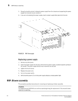
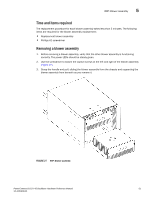
RRP: SFPs and XFPs 5 Replacing the WWN bezel (logo plate) and WWN card ATTENTION Follow ESD precautions ("ESD precautions"). 1. Unpack the new WWN card and save the packaging for the faulty WWN card. 2. Hold the card by the pull tab and insert the WWN cable onto the WWN module until it is fully seated. Use the Phillips screwdriver and the two screws to attach the WWN card to the chassis. NOTE If a serial console session is active, several "removal detected" and "insertion detected" messages display on the console because of the replacement. 3. In the CLI session, enter continue to indicate that the replacement has been completed. Please enter the word `continue' after the new WWN card has been installed: continue Restoring the information to the replacement FRU now, please wait about 20 seconds to complete Verifying the replacement FRU now... WWN card hot swap is now complete. FRU replacement completed successfully! 4. Verify that the WWN card is correctly connected by checking the LED on the WWN card. NOTE The LED might take up to 2 minutes after WWN card installation to begin functioning. 5. Install the WWN bezel. Orient the bezel on the chassis (Figure 28). Insert and tighten the two screws. 6. Pack the faulty WWN card in the packaging provided with the new card and return it to the PowerConnect B-DCX-4S supplier. RRP: SFPs and XFPs NOTE The 8-Gbps SFPs autonegotiate at 2, 4, and 8 Gbps. The 4-Gbps SFPs autonegotiate at 1, 2, and 4 Gbps. To remove an SFP or XFP (FC6-10 blade only) transceiver, pull the bale down and out, sliding the transceiver out of the port or application blade. To install an SFP or XFP, position one of the transceivers so that the key is oriented correctly to the port. Insert the transceiver into the port until it is firmly seated and the latching mechanism clicks. Transceivers are keyed so that they can only be inserted with the correct orientation. If a transceiver does not slide in easily, ensure that it is correctly oriented. The PowerConnect B-DCX-4S comes with a transceiver extraction tool (Figure 29) and holster. The extraction tool is designed to remove transceivers from blades where the space is limited. To use the extraction tool, slide the tool on to the bale of the transceiver and pull it out. PowerConnect B-DCX-4S Backbone Hardware Reference Manual 65 53-1001808-01
-
 1
1 -
2
-
3
-
4
-
5
-
6
-
7
-
8
-
9
-
10
-
11
-
12
-
13
-
14
-
15
-
16
-
17
-
18
-
19
-
20
-
21
-
22
-
23
-
24
-
25
-
26
-
27
-
28
-
29
-
30
-
31
-
32
-
33
-
34
-
35
-
36
-
37
-
38
-
39
-
40
-
41
-
42
-
43
-
44
-
45
-
46
-
47
-
48
-
49
-
50
-
51
-
52
-
53
-
54
-
55
-
56
-
57
-
58
-
59
-
60
-
61
-
62
-
63
-
64
-
65
-
66
-
67
-
68
-
69
-
70
-
71
-
72
-
73
-
 74
74 -
 75
75 -
 76
76 -
 77
77 -
 78
78 -
 79
79 -
 80
80 -
 81
81 -
 82
82 -
 83
83 -
 84
84 -
85
-
86
-
87
-
88
-
89
-
90
-
91
-
92
-
93
-
94
-
95
-
96
-
97
-
98
-
99
-
100
-
101
-
102
-
103
-
104
-
105
-
106
-
107
-
108
-
109
-
110
-
111
-
112
-
113
-
114
-
115
-
116
-
117
-
118
-
119
-
120
-
121
-
122
-
123
-
124
-
125
-
126
-
127
-
128
-
129
-
130
-
131
-
132
-
133
-
134
 |
 |
