Dell PowerConnect B-DCX4S Hardware Reference Guide - Page 28
Items included with the PowerConnect B-DCX-4S
 |
View all Dell PowerConnect B-DCX4S manuals
Add to My Manuals
Save this manual to your list of manuals |
Page 28 highlights
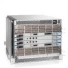
2 Items included with the PowerConnect B-DCX-4S NOTE The PowerConnect B-DCX-4S packaging does not incorporate a wood pallet and pallet brackets. The chassis sits on top of a plastic shipping tray. 2. Use a pallet jack or other assisted lift to transport the new chassis to the installation area. Doorways must be wider than 36 in. (91 cm) to accommodate the chassis. 3. Remove the PowerConnect B-DCX-4S port side exhaust kit, accessory kit, packing foam, and antistatic plastic from the chassis and set aside. 4. Remove the chassis door from the PowerConnect B-DCX-4S. 5. Remove the vertical cable management fingers. 6. Use a lift to raise the chassis to the correct level. If installing the chassis in a cabinet, follow the instructions provided by the port side exhaust kit installation procedure or the appropriate rack kit installation procedure. 7. If applicable, lock the wheels of the lift. 8. Gently slide the chassis onto the final installation surface, ensuring that it remains supported during the transfer. 9. Ensure the chassis can be oriented so that the nonport side has access to intake air (cool). 10. Reinstall the vertical cable management fingers. 11. If ICL cables will not be used, ensure that the ICL sockets in the core switch blades have EMI plugs inserted. 12. Reinstall the chassis door. Items included with the PowerConnect B-DCX-4S The PowerConnect B-DCX-4S ships with the following: • PowerConnect B-DCX-4S chassis, populated with: • Control processor blades (CP8) • Core switch blades (CR4S-8) • Port blades, application blades, and encryption blades (included based on customer specification) • Blade slot filler panels (for slots not filled by blades) • Port side exhaust kit • WWN cards • WWN bezel (logo plate) • Power supplies • Power supply filler panel (included if there is only one power supply) • Blower assemblies • Cable management comb • Chassis door • Accessory kit containing the following items: 14 PowerConnect B-DCX4S Backbone Hardware Reference Manual 53-1001808-01
-
 1
1 -
2
-
3
-
4
-
5
-
6
-
7
-
8
-
9
-
10
-
11
-
12
-
13
-
14
-
15
-
16
-
17
-
18
-
19
-
20
-
21
-
22
-
 23
23 -
 24
24 -
 25
25 -
 26
26 -
 27
27 -
 28
28 -
 29
29 -
 30
30 -
 31
31 -
 32
32 -
 33
33 -
34
-
35
-
36
-
37
-
38
-
39
-
40
-
41
-
42
-
43
-
44
-
45
-
46
-
47
-
48
-
49
-
50
-
51
-
52
-
53
-
54
-
55
-
56
-
57
-
58
-
59
-
60
-
61
-
62
-
63
-
64
-
65
-
66
-
67
-
68
-
69
-
70
-
71
-
72
-
73
-
74
-
75
-
76
-
77
-
78
-
79
-
80
-
81
-
82
-
83
-
84
-
85
-
86
-
87
-
88
-
89
-
90
-
91
-
92
-
93
-
94
-
95
-
96
-
97
-
98
-
99
-
100
-
101
-
102
-
103
-
104
-
105
-
106
-
107
-
108
-
109
-
110
-
111
-
112
-
113
-
114
-
115
-
116
-
117
-
118
-
119
-
120
-
121
-
122
-
123
-
124
-
125
-
126
-
127
-
128
-
129
-
130
-
131
-
132
-
133
-
134
 |
 |
