Dell PowerConnect B-DCX4S Hardware Reference Guide - Page 60
RRP: Port, application, and encryption blades, Time and items required, Removing a blade
 |
View all Dell PowerConnect B-DCX4S manuals
Add to My Manuals
Save this manual to your list of manuals |
Page 60 highlights
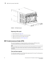
5 RRP: Port, application, and encryption blades RRP: Port, application, and encryption blades This section describes how to remove and replace port, application, and encryption blades. ATTENTION A blade should be removed only when being replaced with another port, application, or encryption blade, or a filler panel ("RRP: Blade filler panel"). Any slot that is not occupied by a blade should be occupied by a filler panel to ensure correct cooling of the chassis and protection from dust. Slots are numbered from 1 through 8, from bottom to top when facing the port side of the PowerConnect B-DCX-4S. Port, application, and encryption blades can be installed in slots 1-2 and 7-8. Time and items required The replacement procedure for each blade takes less than 10 minutes. The following items are required for the blade and filler panel replacement: • ESD (electrostatic discharge) grounding strap • Workstation computer • Replacement blade or filler panel • Phillips screwdriver • Small form-factor pluggable (SFP) or extended form-factor pluggable (XFP, FC10-6 blade only) transceivers (as needed) • Optical cables (as needed) Removing a blade ATTENTION Follow ESD precautions ("ESD precautions"). NOTE The FC8-16, FC8-32, FC8-48, FC10-6, FR4-18i, and FA4-18 blades are compatible with the PowerConnect B-DCX, PowerConnect B-DCX-4S, and the PowerConnect B-48000. The FS8-18 encryption blade and the FX8-24 and FCOE10-24 blades are compatible only with the PowerConnect B-DCX and DCX-4S. 1. Remove the chassis door ("RRP: Chassis door"). 2. Check the power LED, status LED, and port status LED to identify any possible problems. A failed port or application blade can be identified by inspecting the LEDs on the front panel of each blade. See Figure 5 to Figure 13 for LED locations. 3. Establish a Telnet or console session. Before replacing a blade, establish a Telnet or console connection to determine a failure and verify operation after replacement. Use the switchShow command to view the status of blades. 4. Check for adequate cable slack. Ensure there is plenty of cable slack to remove a blade without cable obstruction. 46 PowerConnect B-DCX-4S Backbone Hardware Reference Manual 53-1001808-01
-
 1
1 -
2
-
3
-
4
-
5
-
6
-
7
-
8
-
9
-
10
-
11
-
12
-
13
-
14
-
15
-
16
-
17
-
18
-
19
-
20
-
21
-
22
-
23
-
24
-
25
-
26
-
27
-
28
-
29
-
30
-
31
-
32
-
33
-
34
-
35
-
36
-
37
-
38
-
39
-
40
-
41
-
42
-
43
-
44
-
45
-
46
-
47
-
48
-
49
-
50
-
51
-
52
-
53
-
54
-
 55
55 -
 56
56 -
 57
57 -
 58
58 -
 59
59 -
 60
60 -
 61
61 -
 62
62 -
 63
63 -
 64
64 -
 65
65 -
66
-
67
-
68
-
69
-
70
-
71
-
72
-
73
-
74
-
75
-
76
-
77
-
78
-
79
-
80
-
81
-
82
-
83
-
84
-
85
-
86
-
87
-
88
-
89
-
90
-
91
-
92
-
93
-
94
-
95
-
96
-
97
-
98
-
99
-
100
-
101
-
102
-
103
-
104
-
105
-
106
-
107
-
108
-
109
-
110
-
111
-
112
-
113
-
114
-
115
-
116
-
117
-
118
-
119
-
120
-
121
-
122
-
123
-
124
-
125
-
126
-
127
-
128
-
129
-
130
-
131
-
132
-
133
-
134
 |
 |
