Dell PowerConnect B-DCX4S Hardware Reference Guide - Page 17
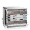
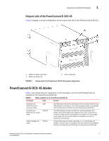
Port side of the PowerConnect B-DCX-4S
 |
View all Dell PowerConnect B-DCX4S manuals
Add to My Manuals
Save this manual to your list of manuals |
Page 17 highlights
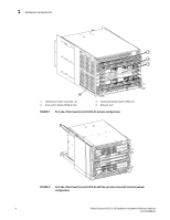
Hardware components 1 NOTE If the any of the following blades are used 220 VAC is required: FS8-18, FX8-24, FCOE10-24. • Modular hot-swappable field replaceable units (FRUs): • Two blower assemblies. • Two 100 to 240 VAC (auto-sensing) power supplies. 240 VAC is recommended for efficiency and high availability. • Two WWN cards. • Small Form-factor Pluggable (SFP and SFP+) optical transceivers (1-, 2-, 4-, and 8-Gbps). • Extended Form-factor Pluggable (XFP) optical transceivers (10-Gbps). NOTE The 8-Gbps SFPs autonegotiate at 2, 4, and 8 Gbps. The 4-Gbps SFPs autonegotiate at 1, 2, and 4 Gbps. • Blades that are serviced from the port side of the PowerConnect B-DCX-4S. Blowers, power supplies, and power cables that are serviced from the nonport side. • World Wide Name (WWN) cards on the nonport side, with WWN status LEDs located under the bezel. • Improved cable management using two vertical cable management fingers and a redesigned chassis door. • Constant intake and FRU temperature monitoring. • Redundant AC primary power connections to ensure high availability. Each power supply has its own connector. Port side of the PowerConnect B-DCX-4S NOTE Airflow in the PowerConnect B-DCX-4S is from the nonport side to the left side of the chassis (viewed from the port side) and out the exhaust vent. If you use the Port Side Exhaust Kit the air vents on the port side of the chassis (see Figure 2). Figure 1 displays a sample configuration of the port side of the PowerConnect B-DCX-4S. PowerConnect B-DCX-4S Backbone Hardware Reference Manual 3 53-1001808-01
-
 1
1 -
2
-
3
-
4
-
5
-
6
-
7
-
8
-
9
-
10
-
11
-
 12
12 -
 13
13 -
 14
14 -
 15
15 -
 16
16 -
 17
17 -
 18
18 -
 19
19 -
 20
20 -
 21
21 -
 22
22 -
23
-
24
-
25
-
26
-
27
-
28
-
29
-
30
-
31
-
32
-
33
-
34
-
35
-
36
-
37
-
38
-
39
-
40
-
41
-
42
-
43
-
44
-
45
-
46
-
47
-
48
-
49
-
50
-
51
-
52
-
53
-
54
-
55
-
56
-
57
-
58
-
59
-
60
-
61
-
62
-
63
-
64
-
65
-
66
-
67
-
68
-
69
-
70
-
71
-
72
-
73
-
74
-
75
-
76
-
77
-
78
-
79
-
80
-
81
-
82
-
83
-
84
-
85
-
86
-
87
-
88
-
89
-
90
-
91
-
92
-
93
-
94
-
95
-
96
-
97
-
98
-
99
-
100
-
101
-
102
-
103
-
104
-
105
-
106
-
107
-
108
-
109
-
110
-
111
-
112
-
113
-
114
-
115
-
116
-
117
-
118
-
119
-
120
-
121
-
122
-
123
-
124
-
125
-
126
-
127
-
128
-
129
-
130
-
131
-
132
-
133
-
134
 |
 |
