Dell PowerConnect B-DCX4S Hardware Reference Guide - Page 73
RRP: Power supply, Time and items required, Identification, Removing a power supply
 |
View all Dell PowerConnect B-DCX4S manuals
Add to My Manuals
Save this manual to your list of manuals |
Page 73 highlights
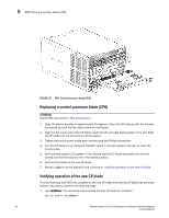
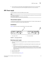
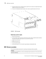
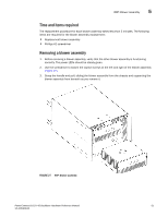
RRP: Power supply 5 8. Pack the faulty core switch blade in the packaging provided with the new core switch blade, and contact the PowerConnect B-DCX-4S supplier to determine the return procedure. RRP: Power supply Use this procedure to remove and replace a power supply. NOTE The PowerConnect B-DCX-4S can continue operating during the replacement if the second 220 VAC power supply is operating. DCX-4S power supplies are 100-240 VAC, auto-sensing. Time and items required The replacement procedure for each power supply takes less than 5 minutes. A power supply unit or filler panel is required for the power supply replacement. Identification Figure 25 shows the location and identification of the power supplies. 1 Power supply 1 (PS1) FIGURE 25 Power supply identification 2 Power supply 2 (PS2)) Removing a power supply 1. Perform the appropriate following action based on whether the PowerConnect B-DCX-4S is operating: • If the PowerConnect B-DCX-4S is not operating during the replacement procedure, go to step 2. • If the PowerConnect B-DCX-4S is operating and will continue to operate during the replacement, check the power LEDs to verify that the minimum number of power supplies is functioning. A fully populated PowerConnect B-DCX-4S requires a minimum of one power supply at all times. 2. Turn off the power switch. 3. Remove the power cord. 4. Loosen the thumb screw (Figure 26). PowerConnect B-DCX-4S Backbone Hardware Reference Manual 59 53-1001808-01
-
 1
1 -
2
-
3
-
4
-
5
-
6
-
7
-
8
-
9
-
10
-
11
-
12
-
13
-
14
-
15
-
16
-
17
-
18
-
19
-
20
-
21
-
22
-
23
-
24
-
25
-
26
-
27
-
28
-
29
-
30
-
31
-
32
-
33
-
34
-
35
-
36
-
37
-
38
-
39
-
40
-
41
-
42
-
43
-
44
-
45
-
46
-
47
-
48
-
49
-
50
-
51
-
52
-
53
-
54
-
55
-
56
-
57
-
58
-
59
-
60
-
61
-
62
-
63
-
64
-
65
-
66
-
67
-
 68
68 -
 69
69 -
 70
70 -
 71
71 -
 72
72 -
 73
73 -
 74
74 -
 75
75 -
 76
76 -
 77
77 -
 78
78 -
79
-
80
-
81
-
82
-
83
-
84
-
85
-
86
-
87
-
88
-
89
-
90
-
91
-
92
-
93
-
94
-
95
-
96
-
97
-
98
-
99
-
100
-
101
-
102
-
103
-
104
-
105
-
106
-
107
-
108
-
109
-
110
-
111
-
112
-
113
-
114
-
115
-
116
-
117
-
118
-
119
-
120
-
121
-
122
-
123
-
124
-
125
-
126
-
127
-
128
-
129
-
130
-
131
-
132
-
133
-
134
 |
 |
