Dell PowerConnect B-DCX4S Hardware Reference Guide - Page 68
Replacing a control processor blade (CP8), Verifying operation of the new CP blade,
 |
View all Dell PowerConnect B-DCX4S manuals
Add to My Manuals
Save this manual to your list of manuals |
Page 68 highlights
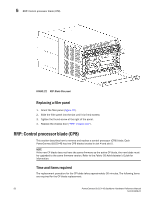
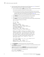
5 RRP: Control processor blade (CP8) FIGURE 23 RRP: Control processor blade (CP8) Replacing a control processor blade (CP8) ATTENTION Follow ESD precautions ("ESD precautions"). 1. Open the ejector handles to approximately 45 degrees. Orient the CP blade so that the handles are toward you and the flat metal side is on the bottom. 2. Align the flat metal side of the CP blade inside the left and right blade guides in the slot. Slide the CP blade into the slot until it is firmly seated. 3. Tighten the thumb screw inside each handle using the Phillips screwdriver. 4. Turn the CP blade on by sliding the ON/OFF switch in the left handle to the left, to cover the thumb screw. 5. Verify that the power LED is green. If not, ensure that the CP blade has power and is firmly seated and that the ejectors are in the locked position. 6. Connect the cables to the new CP blade. 7. Remain logged in to the active CP and continue to "Verifying operation of the new CP blade." Verifying operation of the new CP blade To verify that boot and POST are complete on the new CP blade and that the CP blade has achieved failover redundancy, perform the following steps. 1. Type slotShow. The command output shows the new CP blade as "enabled": switch:admin> slotShow 54 PowerConnect B-DCX-4S Backbone Hardware Reference Manual 53-1001808-01
-
 1
1 -
2
-
3
-
4
-
5
-
6
-
7
-
8
-
9
-
10
-
11
-
12
-
13
-
14
-
15
-
16
-
17
-
18
-
19
-
20
-
21
-
22
-
23
-
24
-
25
-
26
-
27
-
28
-
29
-
30
-
31
-
32
-
33
-
34
-
35
-
36
-
37
-
38
-
39
-
40
-
41
-
42
-
43
-
44
-
45
-
46
-
47
-
48
-
49
-
50
-
51
-
52
-
53
-
54
-
55
-
56
-
57
-
58
-
59
-
60
-
61
-
62
-
 63
63 -
 64
64 -
 65
65 -
 66
66 -
 67
67 -
 68
68 -
 69
69 -
 70
70 -
 71
71 -
 72
72 -
 73
73 -
74
-
75
-
76
-
77
-
78
-
79
-
80
-
81
-
82
-
83
-
84
-
85
-
86
-
87
-
88
-
89
-
90
-
91
-
92
-
93
-
94
-
95
-
96
-
97
-
98
-
99
-
100
-
101
-
102
-
103
-
104
-
105
-
106
-
107
-
108
-
109
-
110
-
111
-
112
-
113
-
114
-
115
-
116
-
117
-
118
-
119
-
120
-
121
-
122
-
123
-
124
-
125
-
126
-
127
-
128
-
129
-
130
-
131
-
132
-
133
-
134
 |
 |
