Dell PowerConnect B-DCX4S Hardware Reference Guide - Page 61
RRP: Blade filler, panel, sliding the slider switch in the left ejector to the right
 |
View all Dell PowerConnect B-DCX4S manuals
Add to My Manuals
Save this manual to your list of manuals |
Page 61 highlights
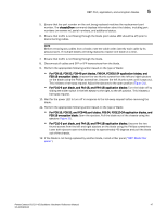
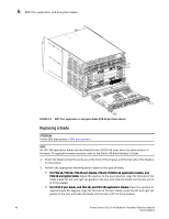
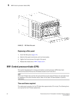
RRP: Port, application, and encryption blades 5 5. Ensure that the part number on the unit being replaced matches the replacement part number. The chassisShow command displays information about the blades, including part numbers (xx-xxxxxxx-xx), serial numbers, and additional status. 6. Ensure that traffic is not flowing through the blade (port status LED should be off) prior to disconnecting cables. NOTE Before removing any cables from a blade, note the cable order (identify each cable by its physical port). If multiple blades are being replaced, replace one blade at a time. 7. Ensure that traffic is not flowing through the blade. 8. Disconnect all cables and SFP or XFP transceivers from the blade. 9. Perform the appropriate following action based on the type of blade: • For FC8-16, FC8-32, FC8-48 port blades, FX8-24, FCOE10-24 application blades, and FS8-18 encryption blade: Unscrew the two thumb screws from the left and right ejectors on the blade using the Phillips screwdriver. Unscrew the left thumb screw until it pops out. This initiates a hot-swap request. Adjust the ejectors to the open position (Figure 21). • For FC10-6 port blade, and FA4-18, and FR4-18i application blades: Turn the blade off by sliding the slider switch in the left ejector to the right, to the off position. This initiates a hot-swap request. 10. Wait for the power LED to turn off in response to the hot-swap request before removing the blade. 11. Perform the appropriate following action based on the type of blade: • For FC8-16, FC8-32, and FC8-48 port blades, FX8-24, FCOE10-24 application blades, and FS8-18 encryption blade: Open the ejectors. Pull the blade out of the chassis using the ejectors (Figure 21). • For FC10-6 port blade, and FA4-18, and FR4-18i application blades: Unscrew the two thumb screws from the left and right ejectors on the blade using the Phillips screwdriver. Lever both ejectors open simultaneously to approximately 45 degrees and pull the blade out of the chassis. 12. If the blade is not being replaced by another blade, install a filler panel ("RRP: Blade filler panel"). PowerConnect B-DCX-4S Backbone Hardware Reference Manual 47 53-1001808-01
-
 1
1 -
2
-
3
-
4
-
5
-
6
-
7
-
8
-
9
-
10
-
11
-
12
-
13
-
14
-
15
-
16
-
17
-
18
-
19
-
20
-
21
-
22
-
23
-
24
-
25
-
26
-
27
-
28
-
29
-
30
-
31
-
32
-
33
-
34
-
35
-
36
-
37
-
38
-
39
-
40
-
41
-
42
-
43
-
44
-
45
-
46
-
47
-
48
-
49
-
50
-
51
-
52
-
53
-
54
-
55
-
 56
56 -
 57
57 -
 58
58 -
 59
59 -
 60
60 -
 61
61 -
 62
62 -
 63
63 -
 64
64 -
 65
65 -
 66
66 -
67
-
68
-
69
-
70
-
71
-
72
-
73
-
74
-
75
-
76
-
77
-
78
-
79
-
80
-
81
-
82
-
83
-
84
-
85
-
86
-
87
-
88
-
89
-
90
-
91
-
92
-
93
-
94
-
95
-
96
-
97
-
98
-
99
-
100
-
101
-
102
-
103
-
104
-
105
-
106
-
107
-
108
-
109
-
110
-
111
-
112
-
113
-
114
-
115
-
116
-
117
-
118
-
119
-
120
-
121
-
122
-
123
-
124
-
125
-
126
-
127
-
128
-
129
-
130
-
131
-
132
-
133
-
134
 |
 |
