Dell PowerConnect B-DCX4S Hardware Reference Guide - Page 43
Monitor System Components, In this Monitoring overview, Determining the status of a port
 |
View all Dell PowerConnect B-DCX4S manuals
Add to My Manuals
Save this manual to your list of manuals |
Page 43 highlights
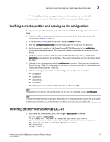
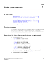
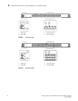
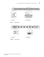
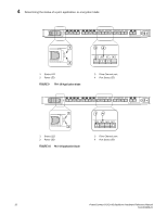
Monitor System Components Chapter 4 In this chapter •Monitoring overview 29 •Determining the status of a port, application, or encryption blade 29 •Determining the status of a control processor blade (CP8 36 •Determining status of a core switch blade (CR4S-8 38 •Determining the status of a power supply 39 •Determining the status of a blower assembly 40 •Determining the status of a WWN card 41 Monitoring overview The PowerConnect B-DCX-4S is engineered for reliability and requires no routine operational steps or maintenance. This chapter provides information about determining the status of each component using LEDs and CLI commands. Refer to the Web Tools Administrator's Guide and the Fabric OS Administrator's Guide for additional information. Determining the status of a port, application, or encryption blade 1. Check the LEDs on the blade. • Figure 5 illustrates the FC8-16 port blade. • Figure 6 illustrates the FC8-32 port blade. • Figure 7 illustrates the FC8-48 port blade. • Figure 8 illustrates the FC10-6 port blade. • Figure 9 illustrates the FR4-18i application blade. • Figure 10 illustrates the FA4-18 application blade. • Figure 11 illustrates the FS8-18 encryption blade. • Figure 12 illustrates the FX8-24 extension blade. • Figure 13 illustrates the FCOE10-24 FCOE blade. The LED patterns may temporarily change during POST and other diagnostic tests. For information about how to interpret the LED patterns, see Table 4. 2. Check the blade status by entering slotShow. PowerConnect B-DCX4S Backbone Hardware Reference Manual 29 53-1001808-01
-
 1
1 -
2
-
3
-
4
-
5
-
6
-
7
-
8
-
9
-
10
-
11
-
12
-
13
-
14
-
15
-
16
-
17
-
18
-
19
-
20
-
21
-
22
-
23
-
24
-
25
-
26
-
27
-
28
-
29
-
30
-
31
-
32
-
33
-
34
-
35
-
36
-
37
-
 38
38 -
 39
39 -
 40
40 -
 41
41 -
 42
42 -
 43
43 -
 44
44 -
 45
45 -
 46
46 -
 47
47 -
 48
48 -
49
-
50
-
51
-
52
-
53
-
54
-
55
-
56
-
57
-
58
-
59
-
60
-
61
-
62
-
63
-
64
-
65
-
66
-
67
-
68
-
69
-
70
-
71
-
72
-
73
-
74
-
75
-
76
-
77
-
78
-
79
-
80
-
81
-
82
-
83
-
84
-
85
-
86
-
87
-
88
-
89
-
90
-
91
-
92
-
93
-
94
-
95
-
96
-
97
-
98
-
99
-
100
-
101
-
102
-
103
-
104
-
105
-
106
-
107
-
108
-
109
-
110
-
111
-
112
-
113
-
114
-
115
-
116
-
117
-
118
-
119
-
120
-
121
-
122
-
123
-
124
-
125
-
126
-
127
-
128
-
129
-
130
-
131
-
132
-
133
-
134
 |
 |
