Dell PowerEdge 1950 Hardware Owner's Manual (PDF) - Page 115
Jumpers and Connectors, System Board Jumpers
 |
View all Dell PowerEdge 1950 manuals
Add to My Manuals
Save this manual to your list of manuals |
Page 115 highlights
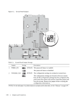
6 Jumpers and Connectors This section provides specific information about the system jumpers. It also provides some basic information on jumpers and switches and describes the connectors on the various boards in the system. System Board Jumpers Figure 6-1 shows the location of the configuration jumpers on the system board. Table 6-1 lists the jumper settings. NOTE: To access the jumpers, remove the system board cooling shroud by lifting the release latch and sliding the shroud towards the front of the system. See Figure 3-13. NOTE: Lift up the memory module airflow shroud for easy access to the jumpers. Jumpers and Connectors 115
-
 1
1 -
2
-
3
-
4
-
5
-
6
-
7
-
8
-
9
-
10
-
11
-
12
-
13
-
14
-
15
-
16
-
17
-
18
-
19
-
20
-
21
-
22
-
23
-
24
-
25
-
26
-
27
-
28
-
29
-
30
-
31
-
32
-
33
-
34
-
35
-
36
-
37
-
38
-
39
-
40
-
41
-
42
-
43
-
44
-
45
-
46
-
47
-
48
-
49
-
50
-
51
-
52
-
53
-
54
-
55
-
56
-
57
-
58
-
59
-
60
-
61
-
62
-
63
-
64
-
65
-
66
-
67
-
68
-
69
-
70
-
71
-
72
-
73
-
74
-
75
-
76
-
77
-
78
-
79
-
80
-
81
-
82
-
83
-
84
-
85
-
86
-
87
-
88
-
89
-
90
-
91
-
92
-
93
-
94
-
95
-
96
-
97
-
98
-
99
-
100
-
101
-
102
-
103
-
104
-
105
-
106
-
107
-
108
-
109
-
 110
110 -
 111
111 -
 112
112 -
 113
113 -
 114
114 -
 115
115 -
 116
116 -
 117
117 -
 118
118 -
 119
119 -
 120
120 -
121
-
122
-
123
-
124
-
125
-
126
-
127
-
128
-
129
-
130
-
131
-
132
-
133
-
134
-
135
-
136
-
137
-
138
-
139
-
140
-
141
-
142
-
143
-
144
-
145
-
146
-
147
-
148
-
149
-
150
-
151
-
152
-
153
-
154
-
155
-
156
-
157
-
158
-
159
-
160
 |
 |

Jumpers and Connectors
115
6
Jumpers and Connectors
This section provides specific information about the system jumpers. It also provides some basic
information on jumpers and switches and describes the connectors on the various boards in the system.
System Board Jumpers
Figure 6-1 shows the location of the configuration jumpers on the system board. Table 6-1 lists the
jumper settings.
NOTE:
To access the jumpers, remove the system board cooling shroud by lifting the release latch and
sliding the shroud towards the front of the system. See Figure 3-13.
NOTE:
Lift up the memory module airflow shroud for easy access to the jumpers.