Dell PowerEdge 1950 Hardware Owner's Manual (PDF) - Page 57
Attach any cables from the internal storage daughter card to the backplane
 |
View all Dell PowerEdge 1950 manuals
Add to My Manuals
Save this manual to your list of manuals |
Page 57 highlights
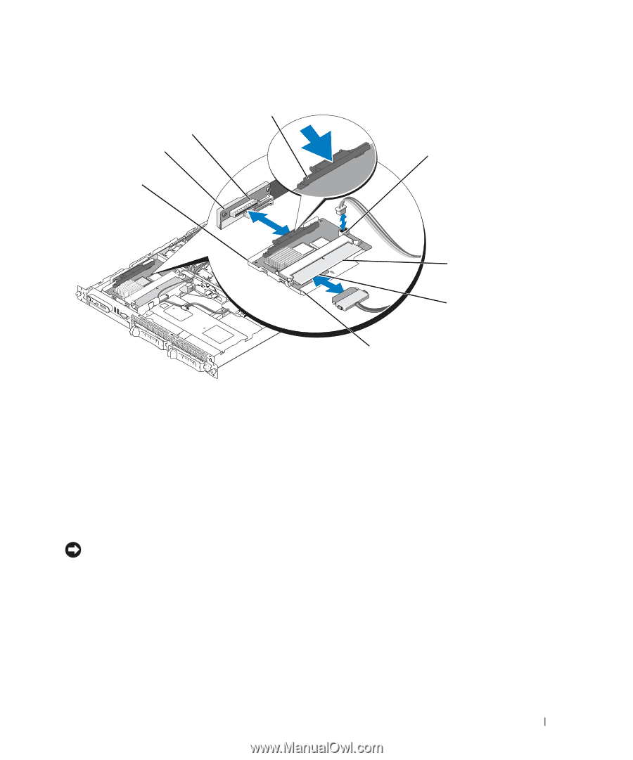
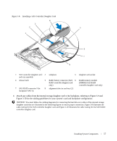
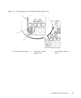
Figure 3-8. Installing a SAS Controller Daughter Card 4 3 2 5 1 6 7 8 1 SAS controller daughter card 2 and tray assembly 4 release latch 5 7 SAS RAID connector 0 (to 8 backplane SAS A) sideplane 3 RAID battery connector (SAS 6 RAID controller daughter card only) alignment slots in card tray (2) daughter card socket RAID memory module (DIMM) (SAS RAID controller daughter card only) 4 Attach any cables from the internal storage daughter card to the backplane, referring to Figure 3-9 and Figure 3-10 for the cabling guidelines for your system's card and backplane configuration. NOTICE: You must follow the cabling diagrams for connecting the hard drives to either of the internal storage daughter cards that are illustrated in the following figures to ensure proper connection. Figure 3-9 illustrates the cable routing for the SAS controller daughter card and Figure 3-10 illustrates the cable routing for the SAS RAID controller daughter card. Installing System Components 57
-
 1
1 -
2
-
3
-
4
-
5
-
6
-
7
-
8
-
9
-
10
-
11
-
12
-
13
-
14
-
15
-
16
-
17
-
18
-
19
-
20
-
21
-
22
-
23
-
24
-
25
-
26
-
27
-
28
-
29
-
30
-
31
-
32
-
33
-
34
-
35
-
36
-
37
-
38
-
39
-
40
-
41
-
42
-
43
-
44
-
45
-
46
-
47
-
48
-
49
-
50
-
51
-
 52
52 -
 53
53 -
 54
54 -
 55
55 -
 56
56 -
 57
57 -
 58
58 -
 59
59 -
 60
60 -
 61
61 -
 62
62 -
63
-
64
-
65
-
66
-
67
-
68
-
69
-
70
-
71
-
72
-
73
-
74
-
75
-
76
-
77
-
78
-
79
-
80
-
81
-
82
-
83
-
84
-
85
-
86
-
87
-
88
-
89
-
90
-
91
-
92
-
93
-
94
-
95
-
96
-
97
-
98
-
99
-
100
-
101
-
102
-
103
-
104
-
105
-
106
-
107
-
108
-
109
-
110
-
111
-
112
-
113
-
114
-
115
-
116
-
117
-
118
-
119
-
120
-
121
-
122
-
123
-
124
-
125
-
126
-
127
-
128
-
129
-
130
-
131
-
132
-
133
-
134
-
135
-
136
-
137
-
138
-
139
-
140
-
141
-
142
-
143
-
144
-
145
-
146
-
147
-
148
-
149
-
150
-
151
-
152
-
153
-
154
-
155
-
156
-
157
-
158
-
159
-
160
 |
 |