Dell PowerEdge 1950 Hardware Owner's Manual (PDF) - Page 52
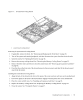
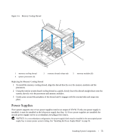
Memory Cooling Shroud, Removing the Memory Cooling Shroud
 |
View all Dell PowerEdge 1950 manuals
Add to My Manuals
Save this manual to your list of manuals |
Page 52 highlights
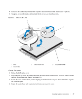
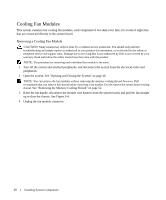
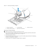
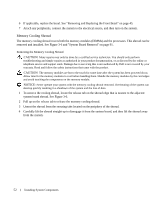
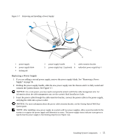
6 If applicable, replace the bezel. See "Removing and Replacing the Front Bezel" on page 45. 7 Attach any peripherals, connect the system to the electrical source, and then turn on the system. Memory Cooling Shroud The memory cooling shroud covers both the memory modules (DIMMs) and the processors. This shroud can be removed and installed. See Figure 3-6 and "System Board Removal" on page 91. Removing the Memory Cooling Shroud CAUTION: Many repairs may only be done by a certified service technician. You should only perform troubleshooting and simple repairs as authorized in your product documentation, or as directed by the online or telephone service and support team. Damage due to servicing that is not authorized by Dell is not covered by your warranty. Read and follow the safety instructions that came with the product. CAUTION: The memory modules are hot to the touch for some time after the system has been powered down. Allow time for the memory modules to cool before handling them. Handle the memory modules by the card edges and avoid touching the components on the memory module. NOTICE: Never operate your system with the memory cooling shroud removed. Overheating of the system can develop quickly resulting in a shutdown of the system and the loss of data. 1 To remove the cooling shroud, locate the release tab on the shroud edge that is nearest to the adjacent system board shroud. See Figure 3-6. 2 Pull up on the release tab to release the memory cooling shroud. 3 Unseat the shroud from the securing tabs located on the periphery of the shroud. 4 Carefully lift the shroud straight up to disengage it from the system board, and then lift the shroud away from the system. 52 Installing System Components
-
 1
1 -
2
-
3
-
4
-
5
-
6
-
7
-
8
-
9
-
10
-
11
-
12
-
13
-
14
-
15
-
16
-
17
-
18
-
19
-
20
-
21
-
22
-
23
-
24
-
25
-
26
-
27
-
28
-
29
-
30
-
31
-
32
-
33
-
34
-
35
-
36
-
37
-
38
-
39
-
40
-
41
-
42
-
43
-
44
-
45
-
46
-
 47
47 -
 48
48 -
 49
49 -
 50
50 -
 51
51 -
 52
52 -
 53
53 -
 54
54 -
 55
55 -
 56
56 -
 57
57 -
58
-
59
-
60
-
61
-
62
-
63
-
64
-
65
-
66
-
67
-
68
-
69
-
70
-
71
-
72
-
73
-
74
-
75
-
76
-
77
-
78
-
79
-
80
-
81
-
82
-
83
-
84
-
85
-
86
-
87
-
88
-
89
-
90
-
91
-
92
-
93
-
94
-
95
-
96
-
97
-
98
-
99
-
100
-
101
-
102
-
103
-
104
-
105
-
106
-
107
-
108
-
109
-
110
-
111
-
112
-
113
-
114
-
115
-
116
-
117
-
118
-
119
-
120
-
121
-
122
-
123
-
124
-
125
-
126
-
127
-
128
-
129
-
130
-
131
-
132
-
133
-
134
-
135
-
136
-
137
-
138
-
139
-
140
-
141
-
142
-
143
-
144
-
145
-
146
-
147
-
148
-
149
-
150
-
151
-
152
-
153
-
154
-
155
-
156
-
157
-
158
-
159
-
160
 |
 |