Dell PowerEdge 1950 Hardware Owner's Manual (PDF) - Page 50
Removing the Plastic Fan Guide, Cooling Shrouds, System Board Cooling Shroud
 |
View all Dell PowerEdge 1950 manuals
Add to My Manuals
Save this manual to your list of manuals |
Page 50 highlights
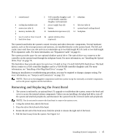
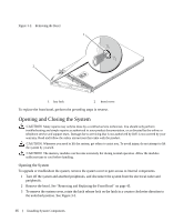
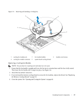
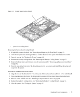
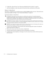
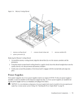
Removing the Plastic Fan Guide NOTE: The plastic fan guide is mounted to the chassis between the fans. NOTE: You may need to remove the system from the rack. 1 Remove the cooling fan modules. See "Removing a Cooling Fan Module" on page 48. 2 Remove the system from the rack. See the Rack Installation Guide for your system. 3 Place the system upside-down on a flat surface. 4 Using a #2 Phillips screwdriver, remove the two screws from the bottom of the chassis that secure the fan bracket. 5 Turn the system right-side up, place it on a flat surface, and then remove the fan bracket. Replacing the Plastic Fan Guide 1 While the system is out of the rack, and with the top cover removed, place the system on its side on a flat surface. 2 Place the fan bracket into its location inside the chassis. 3 Holding the fan bracket in place, use a #2 Phillips screwdriver to replace the two screws on the bottom of the chassis. 4 Place the system right-side up on a flat surface. 5 Replace the cooling fan modules. See "Replacing a Cooling Fan Module" on page 49. 6 Replace the system in the rack. See the Rack Installation Guide for your system. Cooling Shrouds Your system contains two cooling shrouds. • System board cooling shroud • Memory cooling shroud System Board Cooling Shroud The system board cooling shroud directs airflow over the system memory modules, channeling the air from the four fan modules. See Figure 3-5. 50 Installing System Components
-
 1
1 -
2
-
3
-
4
-
5
-
6
-
7
-
8
-
9
-
10
-
11
-
12
-
13
-
14
-
15
-
16
-
17
-
18
-
19
-
20
-
21
-
22
-
23
-
24
-
25
-
26
-
27
-
28
-
29
-
30
-
31
-
32
-
33
-
34
-
35
-
36
-
37
-
38
-
39
-
40
-
41
-
42
-
43
-
44
-
 45
45 -
 46
46 -
 47
47 -
 48
48 -
 49
49 -
 50
50 -
 51
51 -
 52
52 -
 53
53 -
 54
54 -
 55
55 -
56
-
57
-
58
-
59
-
60
-
61
-
62
-
63
-
64
-
65
-
66
-
67
-
68
-
69
-
70
-
71
-
72
-
73
-
74
-
75
-
76
-
77
-
78
-
79
-
80
-
81
-
82
-
83
-
84
-
85
-
86
-
87
-
88
-
89
-
90
-
91
-
92
-
93
-
94
-
95
-
96
-
97
-
98
-
99
-
100
-
101
-
102
-
103
-
104
-
105
-
106
-
107
-
108
-
109
-
110
-
111
-
112
-
113
-
114
-
115
-
116
-
117
-
118
-
119
-
120
-
121
-
122
-
123
-
124
-
125
-
126
-
127
-
128
-
129
-
130
-
131
-
132
-
133
-
134
-
135
-
136
-
137
-
138
-
139
-
140
-
141
-
142
-
143
-
144
-
145
-
146
-
147
-
148
-
149
-
150
-
151
-
152
-
153
-
154
-
155
-
156
-
157
-
158
-
159
-
160
 |
 |